Regulating valve of axial flow sleeve

A sleeve regulating valve, axial flow technology, applied in the direction of lift valve, valve details, valve device, etc., can solve the problems of assembly and maintenance difficulty, graphite column wear, low safety, etc., to improve the maximum flow capacity, improve the internal Organizational structure, the effect of expanding the adjustable range

Active Publication Date: 2013-05-08
TERRENCE ENERGY
View PDF6 Cites 7 Cited by
  • Summary
  • Abstract
  • Description
  • Claims
  • Application Information

AI Technical Summary

Problems solved by technology

However, due to the integral valve body, it brings a lot of difficulties for assembly and maintenance, especially for the second type of regulating valve, which requires a large number of special tools for maintenance, and the requirements for the quality of assembly and maintenance personnel are too high. At the same time, due to the use of cast valve body, Complex structure, difficult manufacturing, many material defects, low safety
Secondly, although the first type of regulating valve is equipped with a guide sleeve and a graphite column, it still cannot solve the problem of insufficient concentricity of the double seal structure, that is, the eccentric scratch of the valve cage (guide sleeve) and the valve barrel, Graphite column wear, leakage, jamming phenomenon
Third, in the design, too much attention is paid to changing the form of the flow channel, and other factors are not considered properly, including: a. The radial end face seal is set on the valve cylinder, resulting in an unbalanced structure and cannot adapt to high-pressure conditions; b. The inlet of the split valve body 10%-20% or higher than the standard flange inlet, resulting in a decrease in flow capacity

Method used


Image

  • Regulating valve of axial flow sleeve
  • Regulating valve of axial flow sleeve
  • Regulating valve of axial flow sleeve

Examples


Embodiment 1

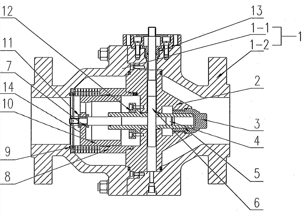
[0025] Such as figure 1 , 3 , 4, an axial flow sleeve regulating valve, including a split valve body 1, a valve core 2, a guide sleeve 5, a valve cage 8, a valve seat 9, a valve cylinder 10 and a transmission valve stem 4 and a transmission valve that can be The rod 4 moves axially in the guide sleeve 5 to drive the valve rod 6, the valve core 2 is installed in the split valve body 1, and one end of the driving valve rod 4 can be axially moved in the guide sleeve 5, and the guide sleeve 5 Inserted in the valve core 2, one end of the driving valve stem 6 passes through the split valve body 1, and the other end is inserted into the valve core 2 to be movably connected with the driving valve stem 4, and the valve cylinder 10 is movably inserted in the valve cage 8, There are several axial flow holes 8-1 on the valve cage 8, and the valve cage 8 is fixedly connected with the valve seat 9, the valve seat 9 is installed in the split valve body 1, and the other end of the transmissi...

Embodiment 2

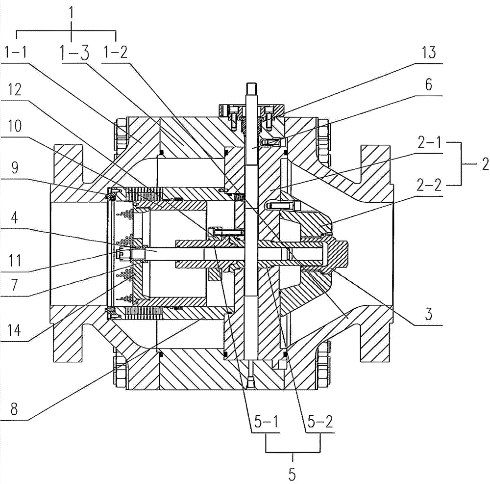
[0029] Such as figure 2 , 3 , 4, an axial flow sleeve regulating valve, including a split valve body 1, a valve core 2, a guide sleeve 5, a valve cage 8, a valve seat 9, a valve cylinder 10 and a transmission valve stem 4 and a transmission valve that can be The rod 4 moves axially in the guide sleeve 5 to drive the valve rod 6, the valve core 2 is installed in the split valve body 1, and one end of the driving valve rod 4 can be axially moved in the guide sleeve 5, and the guide sleeve 5 Inserted in the valve core 2, one end of the driving valve stem 6 passes through the split valve body 1, and the other end is inserted into the valve core 2 to be movably connected with the driving valve stem 4, and the valve cylinder 10 is movably inserted in the valve cage 8, There are several axial flow holes 8-1 on the valve cage 8, and the valve cage 8 is fixedly connected with the valve seat 9, the valve seat 9 is installed in the split valve body 1, and the other end of the transmiss...


PUM


Abstract

The invention discloses a regulating valve of an axial flow sleeve. The regulating valve of the axial flow sleeve comprises a split type valve body, a valve element, a guide sleeve, a valve cage, a valve seat, a valve cylinder, a transmission valve rod and a driving valve rod, wherein the driving valve rod can enable the transmission valve rod to axially move inside the guide sleeve. An automatic valve cylinder aligning mechanism is arranged between the other end of the transmission valve rod and the valve cylinder, the automatic valve cylinder aligning mechanism comprises a center regulating sleeve and a center regulating ring, the center regulating sleeve and the center regulating ring are both supported on the transmission valve rod, and a moving groove with two sides closed is formed between the center regulating sleeve and the center regulating ring. A valve cylinder cover is fixedly connected on the valve cylinder, the valve cylinder is clamped inside the moving groove through the valve cover, and the valve cylinder can move on the axial direction and the radical direction of the transmission valve rod inside the moving groove through the valve cylinder cover. The valve cylinder and the valve cage of the regulating valve of the axial flow sleeve can regulate center automatically, the matching precision of the valve cylinder and the valve cage is improved, a jamming phenomenon is not prone to occurring, a service life is long, and reliability is high.

Description

technical field [0001] The invention relates to an axial flow sleeve regulating valve, which belongs to the technical field of automatic control and is mainly used in industries such as petroleum and natural gas. Background technique [0002] At present, my country's control valve technology has made some progress through continuous introduction, innovation and development. In some industries, axial flow control valves have appeared, which has improved the defects of cut-off control valves in use to a certain extent, but There are still some problems. The advantages and disadvantages of these two types of regulating valves are analyzed below: the cut-off regulating valve is equipped with a valve cage and a valve barrel with a balance hole, which can reduce the unbalanced force of the medium, thereby reducing the size of the actuator , At the same time, different flow characteristics can be obtained, the advantages of reducing fluid noise and spool oscillation, but due to the...

Claims


Application Information

Patent Timeline
Patent Type & Authority Applications(China)
IPC IPC(8): F16K1/00F16K1/32F16K1/48F16K1/36F16K27/02
Inventor 吴伟功连俊林曹宁
Owner TERRENCE ENERGY
Why Eureka
Try Eureka