
Train power supply control system test device and method thereof

A technology for power supply control and system testing, applied in electrical testing/monitoring, etc., can solve problems such as high testing cost, impact of locomotive scheduling, and low testing efficiency, and achieve the effects of low power consumption, cost saving, and good compatibility

Active Publication Date: 2013-05-08
ZHUZHOU CSR TIMES ELECTRIC CO LTD
View PDF3 Cites 26 Cited by
  • Summary
  • Abstract
  • Description
  • Claims
  • Application Information

AI Technical Summary

Problems solved by technology

[0007] (1) The test items of the existing train power supply control system are not complete enough, especially the protection function and logic function test cannot be realized;
[0008] (2) The cost of the load test bench of the train power supply cabinet in the prior art is relatively high, the price of a single unit is basically around 700,000-1 million, and each locomotive depot can basically only be equipped with 1-2 sets;
[0009] (3) A load test of the train power supply cabinet in the prior art takes about 2 hours, consumes 500 degrees of electricity, the test cost is high, the test efficiency is low, and it does not support continuous testing;
[0010] (4) In the prior art, the locomotive to be tested needs to be placed on the designated railway track, which has a certain impact on locomotive scheduling

Method used


Image

  • Train power supply control system test device and method thereof
  • Train power supply control system test device and method thereof
  • Train power supply control system test device and method thereof

Examples


Embodiment Construction

[0055] The following will clearly and completely describe the technical solutions in the embodiments of the present invention with reference to the accompanying drawings in the embodiments of the present invention. Obviously, the described embodiments are only part of the embodiments of the present invention, not all of them. Based on the embodiments of the present invention, all other embodiments obtained by persons of ordinary skill in the art without creative efforts fall within the protection scope of the present invention.

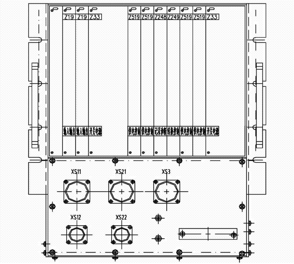
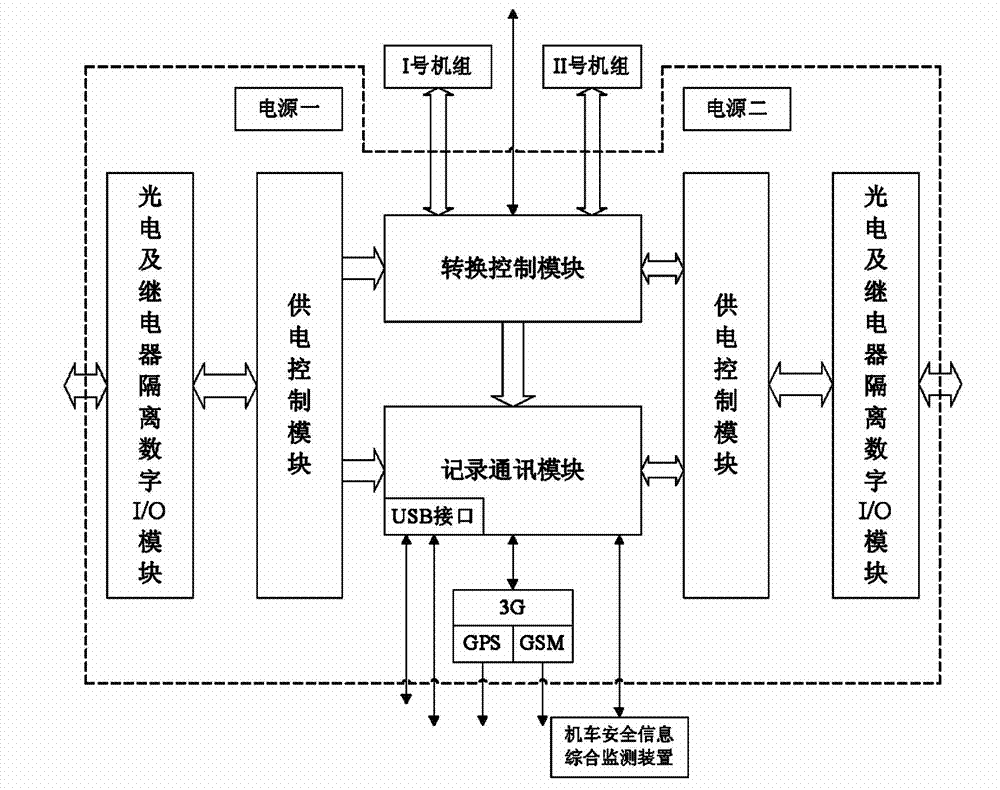
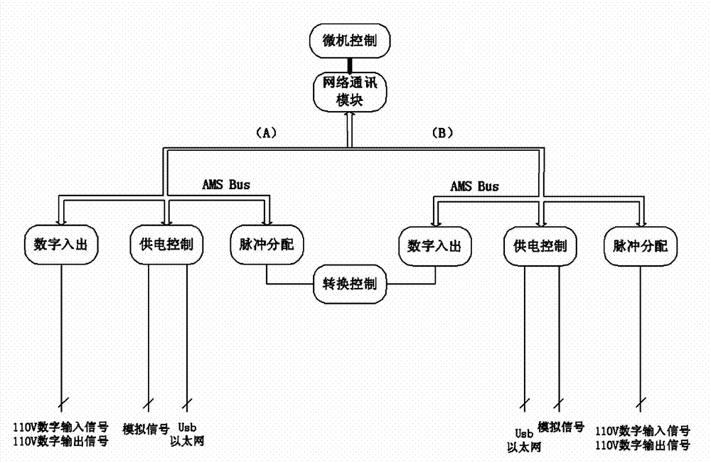
[0056] as attached Figure 5 to attach Figure 9 As shown, a specific embodiment of a test device and method for a train power supply control system of the present invention is provided, and the present invention will be further described below in conjunction with the accompanying drawings and specific embodiments.

[0057] At present, the passenger electric locomotives responsible for pulling passenger trains in various railway bureaus are mainly di...


PUM


Abstract

The invention discloses a train power supply control system test device and a method thereof. The train power supply control system test device comprises a test machine case, a control computer, and an alternating current (AC) power source or a direct current (DC) power source. An external alternating current power source provides power for the test machine case through the AC power source or the DC power source. The test machine case is connected with the control computer. The test machine case collects output signals of an external train power supply control system and transmits data to the control computer to calculate and display. According to the work state of the current train power supply control system and test requirements, the control computer operates a test model of the train power supply control system in real time, sends operation instructions to the test machine case, and outputs corresponding test signals to the train power supply control system. According to the train power supply control system test device and the method thereof, test project is complete, compatibility is good, test is fast and convenient to conduct, regular inspection and test to the train power supply control system can be achieved, and operation reliability of the train power supply control system is improved.

Description

technical field [0001] The invention relates to a power supply control system testing device and a method thereof, in particular to a power supply control system testing device and a method applied to railway train vehicles. Background technique [0002] The train power supply cabinet is a converter device on passenger electric locomotives. It can rectify rated single-phase AC 860V into DC 600V output, and provide working power for air conditioners, ventilators, lighting and other equipment of passenger trains. At present, in order to promote energy saving and consumption reduction of railways and improve transportation efficiency, the Ministry of Railways of my country has canceled power generation cars on a large scale and promoted DC600V train power supply cabinets for electric locomotives. Electric locomotive train power supply cabinets have been used on a large scale on electric locomotives including AC and DC electric locomotives (SS7C / SS7D / SS7E / SS8 / SS9 / SS9G, etc.) and...

Claims


Application Information

Patent Timeline
IPC IPC(8): G05B23/02
Inventor 李小平罗继光黄亮蔡杰李鹏刘小华唐鸿华欧阳天添
Owner ZHUZHOU CSR TIMES ELECTRIC CO LTD
Learn More