Tracing method of solar battery maximum power point

A technology of maximum power point and solar cells, applied in photovoltaic power generation, regulating electric variables, instruments, etc., can solve problems such as inaccurate tracking

Inactive Publication Date: 2013-05-08
CHINA JILIANG UNIV
View PDF4 Cites 6 Cited by
  • Summary
  • Abstract
  • Description
  • Claims
  • Application Information

AI Technical Summary

Problems solved by technology

[0005] Among the above methods, the constant voltage tracking method (CVT) is an approximate maximum power point tracking method, and when the temperature changes, it cannot track accurately

Method used


Image

  • Tracing method of solar battery maximum power point
  • Tracing method of solar battery maximum power point
  • Tracing method of solar battery maximum power point

Examples


Embodiment Construction

[0042] The present invention will be further described below in conjunction with the accompanying drawings and embodiments.

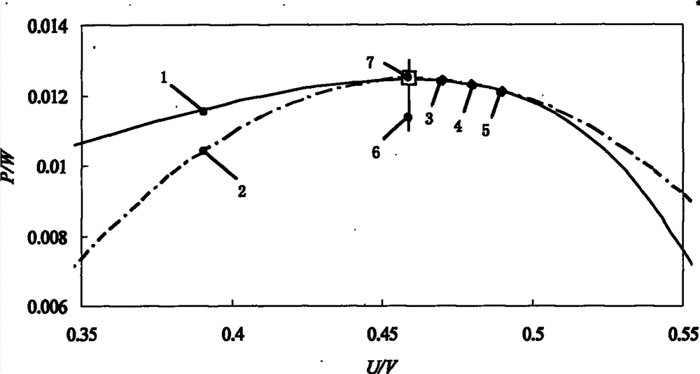
[0043] see figure 1 , the solar cell output power / voltage curve 1 is a symmetrical unimodal curve near the maximum power point, which can be approximated as a parabolic curve with the maximum power point as the vertex and the voltage at the maximum power point as the axis of symmetry. By detecting this part of the curve The last three groups of power / voltage data detection points (U m1 , P m1) 3. Detection point (U m2 , P m2 )4 and detection point (U m3 , P m3 ) 5, to solve the parabolic equation, the extreme point 6 of the parabolic equation is the maximum power point 7 of the solar cell, and the specific operation includes the following steps:

[0044] Step 1, the determination method of three groups of power / voltage data detection points

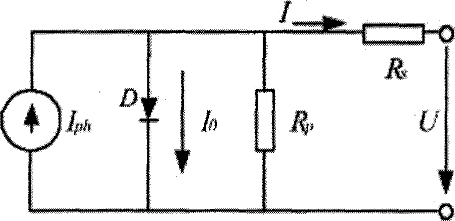
[0045] In the light state, the output characteristics of the solar cell can be approximated to the diode ...


PUM


Abstract

The invention discloses a tracing method of a solar battery maximum power point. A part of curve which is nearby the maximum power point of a solar battery output characteristic power / voltage curve 1 is approximated to a parabola 2, a parabolic equation is solved by using three groups of power / voltage data 3, 4 and 5 on the part of the curve, and an extreme point 6 of the parabolic equation is the maximum power point 7 output by the solar battery.

Description

technical field [0001] The invention relates to a solar cell maximum power point tracking method. Background technique [0002] Solar photovoltaic power generation has the advantages of no pollution, no noise, inexhaustible supply, and no need for production materials except sunlight. It is a green energy with broad prospects and occupies an important position in the future system. [0003] The output power of solar cells is related to light, ambient temperature and load, and there is a unique maximum power point (MPP) under certain light, ambient temperature and load conditions. In order to improve power generation efficiency, it is necessary to track the maximum power point. At present, there are many methods for tracking the maximum power point of solar cells, and the most commonly used methods are constant voltage tracking (CVT), perturbation and observation (P&Q) and incremental conductance (INC). [0004] The principle of the constant voltage tracking method (CVT) is...

Claims


Application Information

Patent Timeline
Patent Type & Authority Applications(China)
IPC IPC(8): G05F1/67
CPCY02E10/58Y02E10/56
Inventor 卫东楼洪
Owner CHINA JILIANG UNIV
Why Eureka
Try Eureka