
Linkage type row pile vibration isolation structure

A vibration isolation and pile top technology, which is applied in special data processing applications, instruments, electrical digital data processing, etc., can solve problems such as the inconformity of the pile row vibration isolation system, and achieve the effect of improving the vibration isolation effect and reducing the amplitude ratio

Inactive Publication Date: 2013-05-08
JIANGSU UNIV
View PDF3 Cites 6 Cited by
  • Summary
  • Abstract
  • Description
  • Claims
  • Application Information

AI Technical Summary

Problems solved by technology

In addition, in the existing studies, due to the limitation of the computer capacity, the piles are all simplified to a limited number of piles. Obviously, this is different from the pile-row vibration isolation system that contains dozens or even hundreds of piles in engineering practice. meets the
Since the number of piles used in the vibration isolation numerical simulation has a significant impact on the vibration isolation effect, there are limitations in using a few piles to simulate the pile-row vibration isolation system

Method used


Image

  • Linkage type row pile vibration isolation structure
  • Linkage type row pile vibration isolation structure
  • Linkage type row pile vibration isolation structure

Examples


Embodiment 1

[0021] The calculation model steps of the present invention are briefly described below.

[0022] According to the Floquet transform method, using the boundary integral equation of the soil in the space domain, the following boundary integral equation of the half-space soil in the wavenumber domain is obtained

[0023] c ij u ~ j ( S II ) ( κ , x ( e ) ) = ∫ Γ S ( e ) U ~ ij ( S ...

Embodiment 2

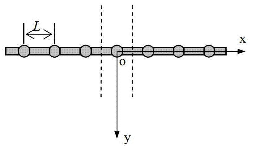
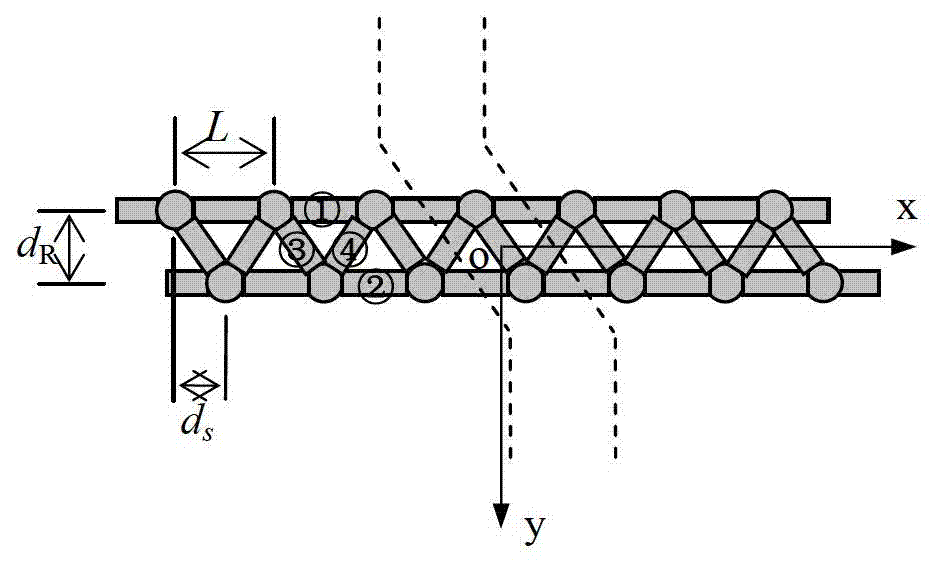
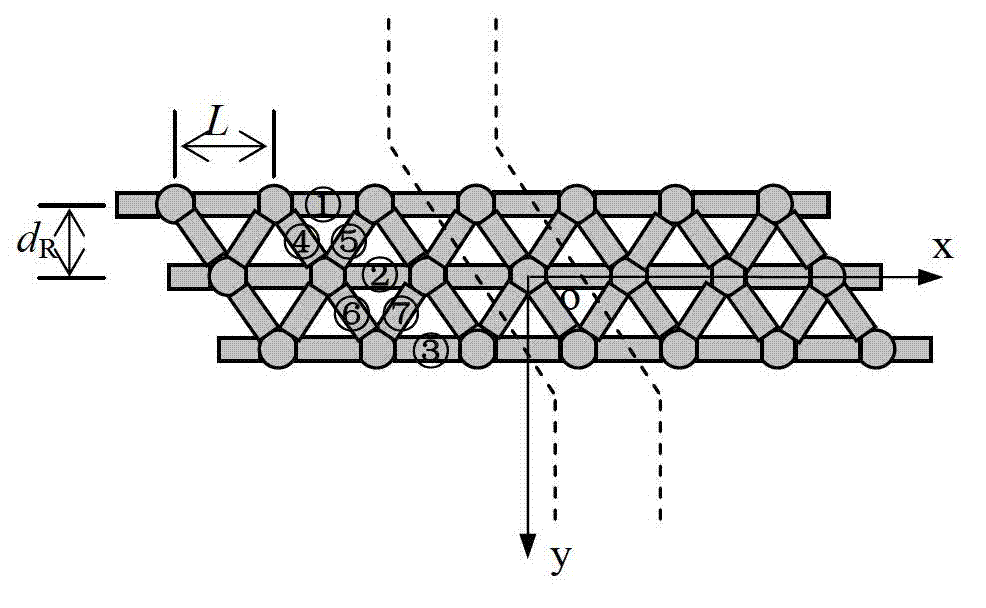
[0072] The following uses the double-row connected pile-row vibration isolation structure as an example to illustrate the improvement of the connected pile-row vibration isolation effect compared to the same free-style pile-row vibration isolation structure.

[0073] Let the row spacing of double-row piles be d r =1.5m, the distance between the centers of adjacent piles in the pile row is L=2.0m, and the two rows of piles are staggered by 1.0m along the direction of the pile row; the pile foundation adopts circular cross-section concrete piles with a length of L p =10m, the diameter is d=1.0m, the shear modulus μ p =1.0×10 10 Pa, density ρ p =2.4×10 3 kg / m 3 , Poisson's ratio ν p =0.2; the shear modulus of half-space soil is μ s =1.0×10 7 Pa, the density is ρ s =2.0×10 3 kg / m 3 , Poisson's ratio ν s =0.35; the pile top connecting beam adopts a rectangular cross-section concrete beam, and the beam width is w b =0.8m, beam height is w b =0.5m, the shear modulus of t...


PUM

PropertyMeasurementUnit
Shear modulusaaaaaaaaaa
Densityaaaaaaaaaa
Shear modulusaaaaaaaaaa

Abstract

The invention relates to a linkage type row pile isolation structure. The structure is provided with a periodic row pile structure on the walking direction of row piles, and pile tops of the row piles are in mutually rigid linkage through linkage beams. Each pile in the same row of the piles is a concrete pile with arbitrary cross section, and is provided with same geometry material parameters; and piles in different rows can have different parameters. The linkage beams in the same groups have same geometry material parameters, and the linkage beams in different groups can have different parameters. Floquet transformation and a boundary element method are adopted, and a pile-soil boundary element model in a wave number domain is built. The linkage beams on the upper portion are processed through a transfer matrix method. The pile-soil boundary element model, coupling conditions and periodic conditions of the pile tops and the beams are adopted, and a calculation model of the linkage type row piles is built. Compared with free type row piles with pile tops not restricted, the linkage type row pile isolation structure can effectively reduce vibration isolation coefficients and improve vibration isolation effects.

Description

technical field [0001] The invention proposes a new type of pile foundation structure for vibration isolation, that is, connected row piles, and uses Floquet transformation and boundary element method to establish a periodic boundary element model of the new type of pile foundation vibration isolation structure. Background technique [0002] In the 21st century, China's modern transportation facilities such as high-speed railways, expressways, subways and light rails are rapidly popularizing. Correspondingly, the vibration problems caused by the above-mentioned transportation facilities have also attracted extensive attention in the engineering field; at the same time, due to machine vibration The vibration problems caused by construction activities such as construction, blasting and piling are also becoming more and more serious, which brings a lot of inconvenience to people's daily life. Therefore, improving the vibration isolation effect of various vibration isolation fac...

Claims


Application Information

Patent Timeline
IPC IPC(8): G06F17/50
Inventor 陆建飞张旭
Owner JIANGSU UNIV
Learn More