Millimeter wave omnidirectional circularly polarized antenna based on circularly polarized loudspeaker

A circularly polarized antenna and millimeter-wave technology, which is applied to antennas, waveguide horns, and radiating element structures, can solve the problems of standing wave bandwidth, narrow axial ratio bandwidth, poor antenna pattern out of roundness, and low radiation efficiency, etc. problem, to achieve the effect of ensuring circular polarization performance, good out-of-roundness of the pattern, and realizing omnidirectional characteristics

Active Publication Date: 2015-04-08
CNGC INST NO 206 OF CHINA ARMS IND GRP
View PDF5 Cites 2 Cited by
  • Summary
  • Abstract
  • Description
  • Claims
  • Application Information

AI Technical Summary

Problems solved by technology

The limitation of this implementation is that the radius of the ring is limited by the overall size of the antenna. In order to achieve omnidirectional radiation, it is necessary to select a suitable number of units. The out-of-roundness of the antenna pattern is not good. In the high frequency band, the antenna loss is large and the radiation efficiency is low

Method used


Image

  • Millimeter wave omnidirectional circularly polarized antenna based on circularly polarized loudspeaker
  • Millimeter wave omnidirectional circularly polarized antenna based on circularly polarized loudspeaker
  • Millimeter wave omnidirectional circularly polarized antenna based on circularly polarized loudspeaker

Examples


Embodiment Construction

[0026] Now in conjunction with embodiment, accompanying drawing, the present invention will be further described:

[0027] This embodiment is divided into two parts to design:

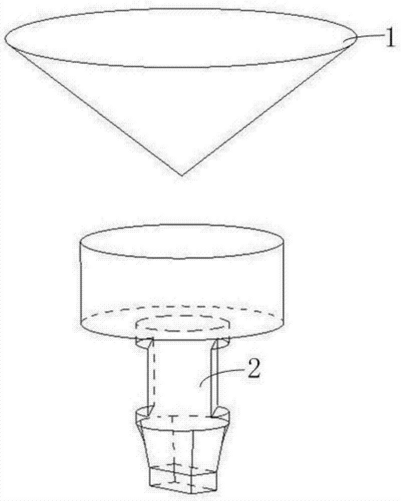
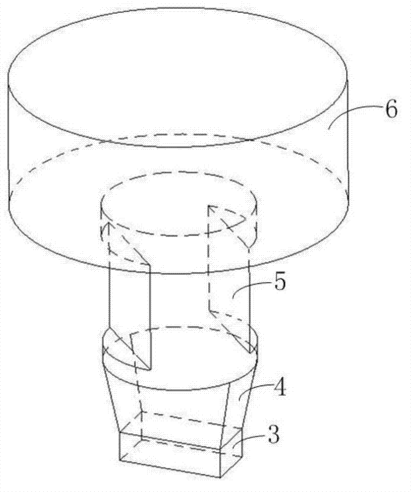
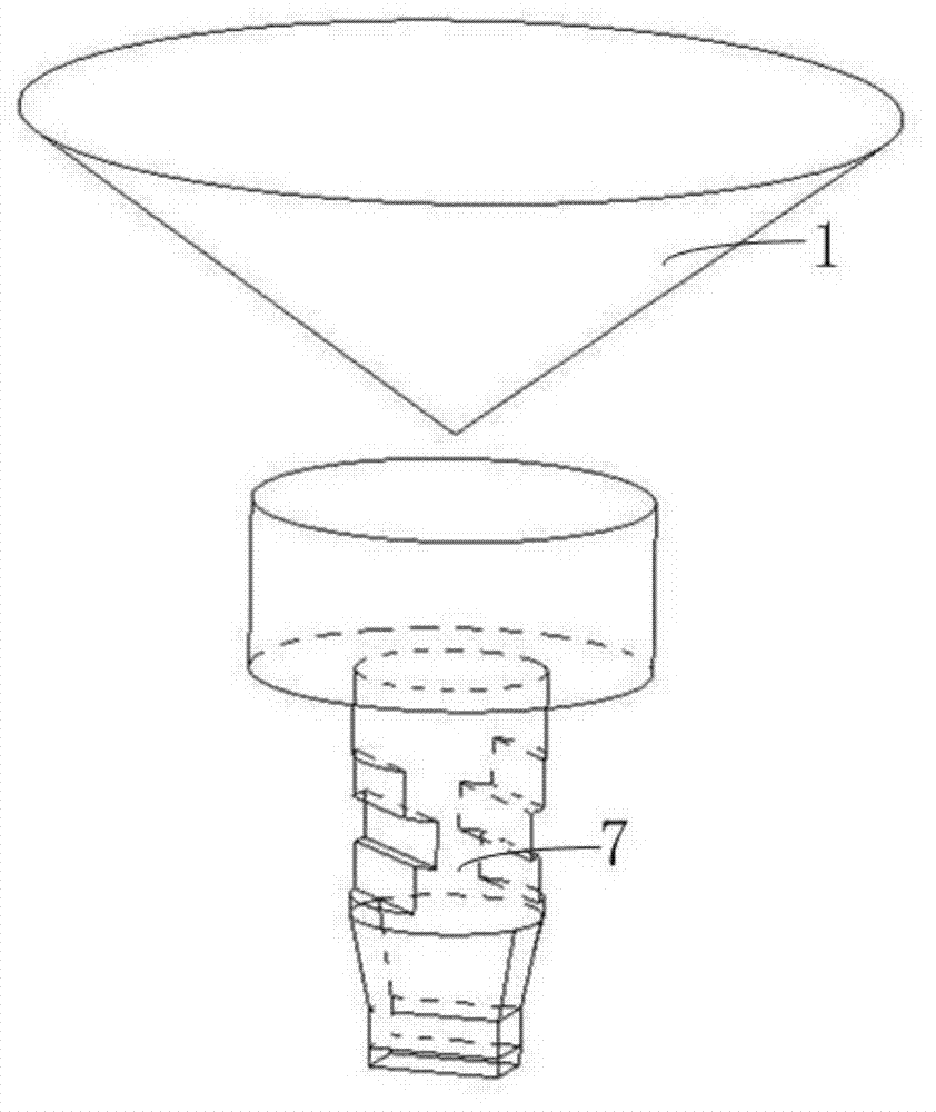
[0028] 1. The design of the millimeter-wave circularly polarized horn: the feed section of the millimeter-wave circularly polarized horn adopts the standard BJ320 waveguide, the input mode is TE01 mode, and the rectangular-circular converter converts the TE10 mode into the TE11 mode suitable for transmission in the circular waveguide . The circular polarizer is realized by the method of loading a metal block with a circular waveguide, which consists of a circular waveguide transmitting the TE11 mode and two metal blocks placed at an angle of 45 degrees to the electric field vector E of the TE11 mode. When the electric field vector passes through the circular polarizer, it presents capacitive and inductive loading effects on the vertical electric field vector and the horizontal electric field vector re...


PUM


Abstract

The invention relates to a millimeter wave omnidirectional circularly polarized antenna based on a circularly polarized loudspeaker. The millimeter wave omnidirectional circularly polarized antenna comprises a millimeter wave circularly polarized loudspeaker, and is characterized by further comprising a metal conical reflective face and the millimeter wave circularly polarized loudspeaker. An output end of the millimeter wave circularly polarized loudspeaker is a standard BJ320 waveguide, and an input mode is a TE10 mode which can be converted into a TE11 mode through a rectangular-circularly convertor. A circular polarization device respectively presents the capacitive function and the inductive load function to a perpendicular electric field vector and a horizontal electric field vector so that phases of the two vectors are lagged and lead, and the fact that waves radiated from an expanded T-shaped metal table has a good circularly polarization characteristic is guaranteed. The circularly polarized waves are radiated on the metal conical reflective face, the main radiation direction of the waves is changed from the axial direction to the radial direction, the direction of the radiation waves rotates reversely, the circularly polarization characteristic is not changed, but the radiation waves are omnidirectional, and circularly polarized radiation in a large angle range on a pitch face is achieved.

Description

technical field [0001] The invention relates to a field of millimeter-wave antennas, in particular to an omnidirectional circularly polarized antenna with an omnidirectional azimuth plane and a wider radiation beam on the elevation plane, and is a millimeter-wave omnidirectional circularly polarized antenna based on a circularly polarized horn . Background technique [0002] The so-called polarization refers to the way that the orientation of the electromagnetic field strength changes with time, and the trajectory described by the inner space of each end point of the electric field strength vector is generally used to represent the polarization of the wave. The so-called circularly polarized antenna means that the direction and magnitude of the electric field in the electromagnetic field radiated by an antenna is not fixed in space, but forms a circle in a plane as time changes. The realization of omnidirectional circular polarization is relatively difficult, and the realiz...

Claims


Application Information

Patent Timeline
Patent Type & Authority Patents(China)
IPC IPC(8): H01Q1/36H01Q13/02H01Q19/12
Inventor 马汉清石俊峰汤畅李超闫云涛李绪平
Owner CNGC INST NO 206 OF CHINA ARMS IND GRP
Why Eureka
Try Eureka