

Method, user equipment and access point of controlling uplink power
A technology of power control and user equipment, applied in the field of communication, can solve problems such as poor signal quality, low channel measurement accuracy, and difficulty in correctly detecting SRS, and achieve the effect of improving accuracy
- Summary
- Abstract
- Description
- Claims
- Application Information
AI Technical Summary
Problems solved by technology
Method used
Image

Examples
Embodiment 1
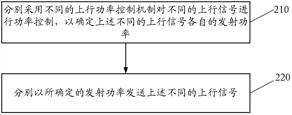
[0101] Figure 4 A schematic flow chart showing a process of uplink power control according to an embodiment of the present invention.
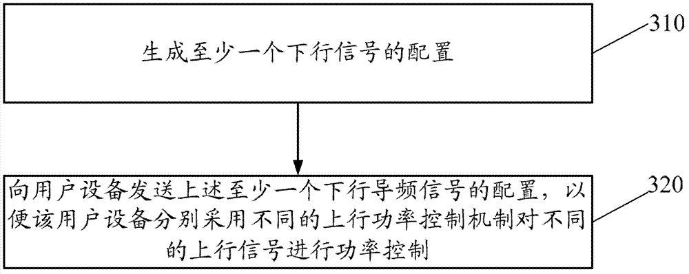
[0102] 410. The access point sends indication signaling to the UE.
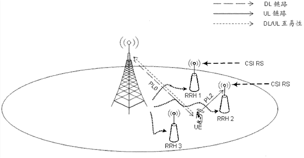
[0103] For example, the foregoing access point may be an eNode B or an RRH, to which the embodiments according to the present invention are not limited. For example, the foregoing access point may also be a relay station or a micro base station. In particular, in a system supporting TDD mode, if there is an RRH within the coverage of the eNode B, the eNode B can send the above indication signaling to the UE, so that the UE sends the eNode B as the target access point Different uplink power control mechanisms can be used for the periodic SRS and the periodic SRS with the RRH as the target access point.
[0104]For example, the above indication signaling is used to instruct the UE to adopt different uplink power control mechanisms when sending different uplink pilot signals ...
Embodiment 2
[0125]Similar to Embodiment 1, in Embodiment 2, the access point issues an indication signaling, and the UE adopts different uplink power control mechanisms when performing power control on different uplink pilot signals according to the above indication signaling, so as to The transmit powers of different uplink pilot signals are determined respectively. The difference from Embodiment 1 is that in Embodiment 1, the power compensation is performed by measuring the path losses of different uplink pilot signals used by different access points respectively, while in Embodiment 2, different uplink pilot signals can be independently set Parameters in the formula for calculating the transmission power of at least one uplink pilot signal in the signal, for example, the power offset P SRS_OFFSET,c (m), path loss compensation factor α c (j) or closed-loop power adjustment f c (i), their values can be different, by setting these parameters independently, it is also possible to perfo...
Embodiment 3
[0137] Figure 5 A schematic diagram showing the configuration of uplink pilot signals according to an embodiment of the present invention.
[0138] Similar to Embodiment 1, in Embodiment 3, the access point sends an indication signaling to the UE, and the UE adopts different uplink power control mechanisms when performing power control on different uplink pilot signals according to the above indication signaling, To determine the respective transmit powers of different uplink pilot signals. Further, still taking the uplink pilot signal as the SRS as an example, refer to Figure 5 , when configuring frequency hopping (hopping), the UE may use different power control mechanisms to perform power control on the SRS according to different subframes, different frequency bands, different sequences, or different antennas.
[0139] For example, in the case that different uplink pilot signals are all periodic SRS, the periodic SRS using the first power control mechanism can be config...
PUM
 Abstract
Description
Claims
Application Information