Mutual transmission method between user equipment and access network system

A user equipment and data transmission technology, applied in the field of communication, can solve problems such as increased core network load

Active Publication Date: 2013-05-08
CHINA UNITED NETWORK COMM GRP CO LTD
View PDF3 Cites 5 Cited by
  • Summary
  • Abstract
  • Description
  • Claims
  • Application Information

AI Technical Summary

Problems solved by technology

[0004] However, as the volume of data traffic continues to increase, more and more traffic converges to the core network, resulting in an increase in the load of the core network

Method used


Image

  • Mutual transmission method between user equipment and access network system
  • Mutual transmission method between user equipment and access network system
  • Mutual transmission method between user equipment and access network system

Examples


Embodiment Construction

[0022] In order to make the purpose, technical solutions and advantages of the embodiments of the present invention clearer, the technical solutions in the embodiments of the present invention will be clearly and completely described below in conjunction with the drawings in the embodiments of the present invention. Obviously, the described embodiments It is a part of embodiments of the present invention, but not all embodiments. Based on the embodiments of the present invention, all other embodiments obtained by persons of ordinary skill in the art without creative efforts fall within the protection scope of the present invention.

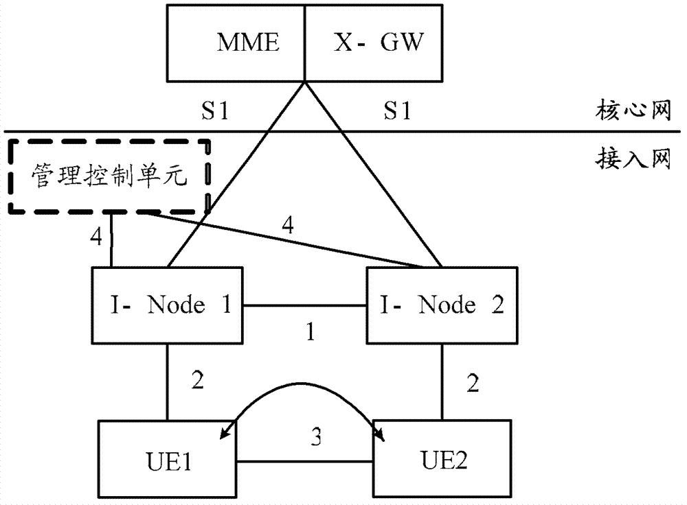
[0023] In order to facilitate the understanding of the technical solution of the present invention, the network architecture to which the technical solution of the present invention is applied is firstly described with an example.

[0024] figure 1 A schematic diagram of a network architecture applied in the method embodiment of the present inven...


PUM


Abstract

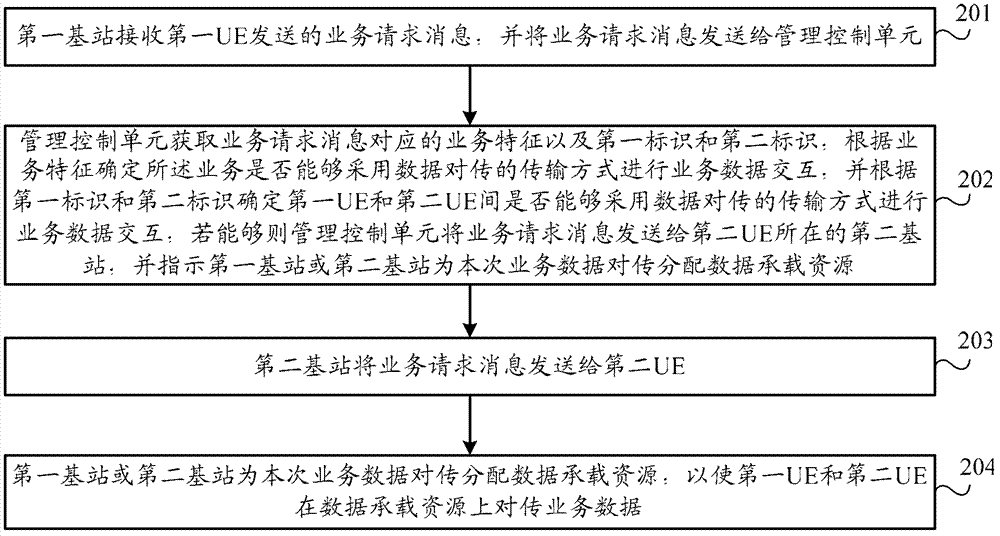
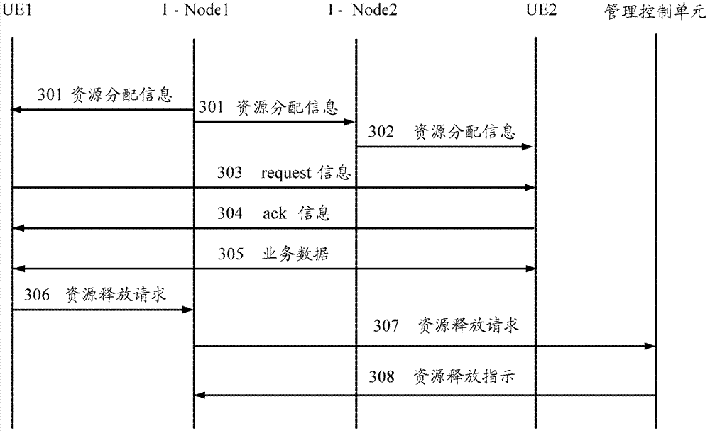
The invention provides a mutual transmission method between user equipment and an access network system. When a management control unit receives service request messages sent by a first user equipment (UE) through a base station, the management control unit can judge whether a transmission mode of data mutual transmission can be conducted to interact service data or not between the first UE and the second UE according to the service request messages, if the data mutual transmission between the first UE and the second UE can be achieved, the management control unit can forward the service request messages to a second base station where the second UE is located, and indicate a first base station or the second base station to distribute carrying resources for the service data mutual transmission, and therefore the first UE and the second UE can conduct local data mutual transmission. Services which can be achieved by local data mutual transmission between the UEs do not need to do service data return through core network, but the business data return can only be done in access network, and therefore loading pressure of the core network can be relieved to a certain degree.

Description

technical field [0001] The present invention relates to communication technology, in particular to a method for intercommunication between user equipment and an access network system. Background technique [0002] At present, when two user equipments (User Equipment, hereinafter referred to as: UE) interact with data services in the communication network, their service data must first be aggregated to the core network through the wireless access network, processed through the core network, and then transmitted through the wireless network. The access network returns and processes service data. [0003] For example, the UE at the sending end can transmit service data to the base station where the UE at the sending end is located, such as a Node B (hereinafter referred to as: NodeB) or an enhanced eNodeB (hereinafter referred to as: I-Node), and the NodeB then transmits the service data through the S1 interface After being uploaded to the core network, the service data is pro...

Claims


Application Information

Patent Timeline
Patent Type & Authority Applications(China)
IPC IPC(8): H04W72/04
Inventor 王健全赵婷婷吕召彪马彰超
Owner CHINA UNITED NETWORK COMM GRP CO LTD
Why Eureka
Try Eureka