Cache-based data transmission methods and apparatuses

a data transmission and cache technology, applied in the field of radio communication technologies, can solve the problems of increasing reducing the efficiency of transmission of massive user data, and limiting the bandwidth resources of communication systems, so as to reduce the load on communication networks caused by massive data, reduce the load on communication networks, and reduce the effect of transmission path length

Active Publication Date: 2019-05-14
SAMSUNG ELECTRONICS CO LTD
View PDF24 Cites 1 Cited by
  • Summary
  • Abstract
  • Description
  • Claims
  • Application Information

AI Technical Summary

Benefits of technology

[0065]As can be seen from the embodiments of the present disclosure, through caching data contents with high popularity and / or long life cycle by a caching node, a transmission path of the data contents may be shortened, and the load pressure of communication networks caused by massive data may be relieved.

Problems solved by technology

As well known, transmission capacity in a communication system is limited by bandwidth resources.
Accordingly, how to transmit massive user data with high efficiency for the purpose of relieving the load pressure of the radio access network, transport network and bearer network caused by ever-growing mobile traffic increase has become an urgent issue.
However, these conventional solutions for solving the problem caused by the increase of mobile traffic all dramatically increase the establishment costs of operator networks, that is to say, probably revenue cannot scale with the increase of data volume.
However, recent analysis reveals that in massive data transmitted in the mobile communication network, many data contents hold a large number of users' common interest.
If these data contents are transmitted on an air interface through a conventional point-to-point transmission mode, resources may be wasted.
However, there is still a problem, that is, these users may need the data at different time points.
Besides the transmission pressure of air interface, the increase of mobile traffic causes the transmission pressure of backhaul link, where data contents with high popularity and long life cycle are transmitted repeatedly between the radio access network and a network data center, thereby causing the unnecessary waste of link resources.

Method used


Image

  • Cache-based data transmission methods and apparatuses
  • Cache-based data transmission methods and apparatuses
  • Cache-based data transmission methods and apparatuses

Examples


first embodiment

[0088]A first embodiment is implemented as follows.

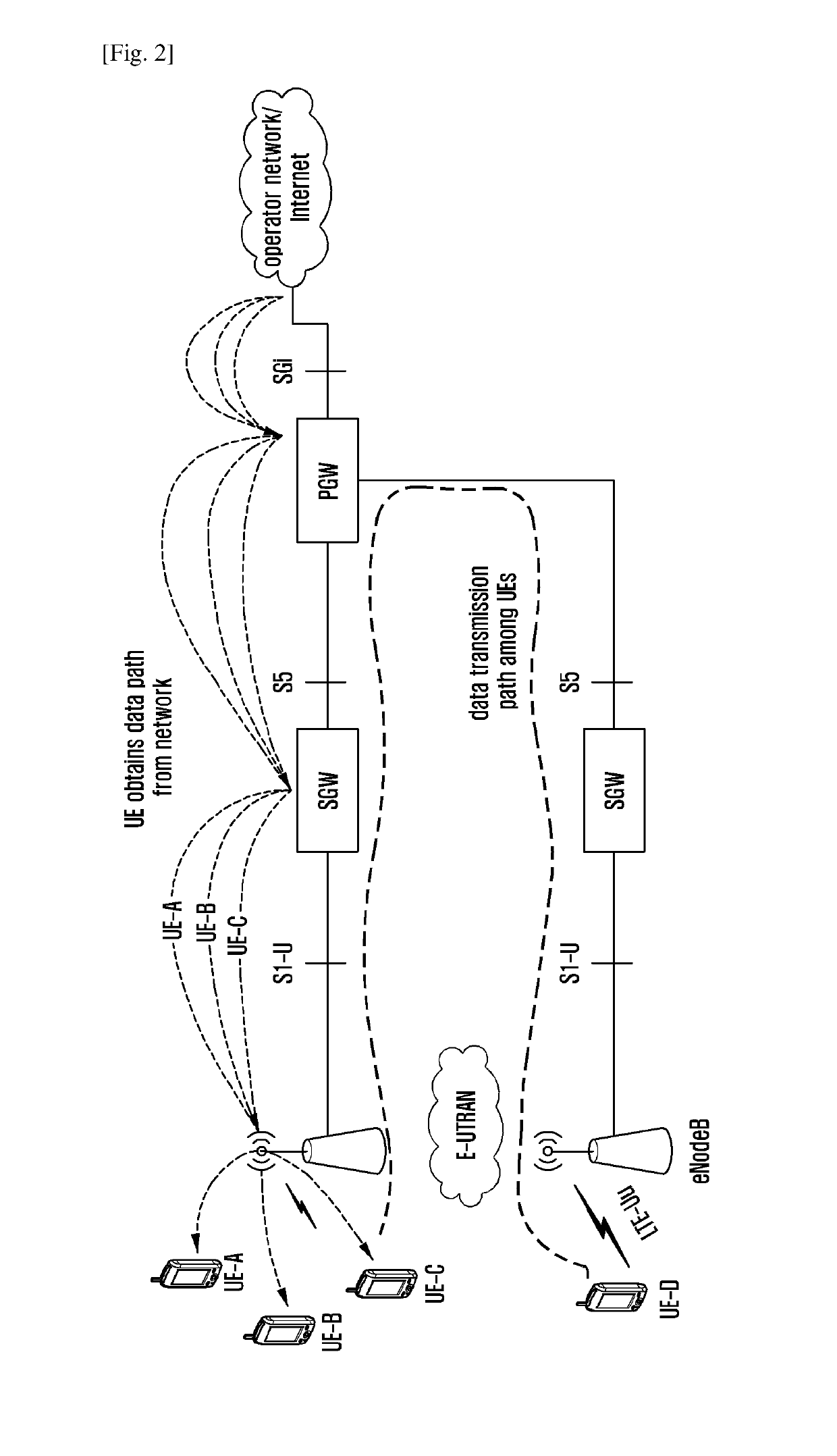
[0089]In this embodiment, a caching node is located in an eNodeB. A cache-based data transmission method in a LTE system is described with reference to FIGS. 3 and 4.

[0090]FIG. 4 is a flowchart illustrating a cache-based data transmission method according to the first embodiment of the present disclosure. The method includes following blocks.

[0091]At block 401, a caching node is located in an eNodeB, and the eNodeB reports a caching capability through an interface connected to a MME. The caching capability includes cache size configuration information.

[0092]At block 402, a data analyzing center analyzes data of an operator network / Internet, gives the data with a data property parameter such as popularity and life cycle related to data repetition transmission probability and / or cache utilization, and sends the data property parameter to the MME. Or, the data analyzing center performs general analysis for the data, and thus the data p...

second embodiment

[0102]A second embodiment is implemented as follows.

[0103]In this embodiment, a caching node is still located in an eNodeB. A cache-based data transmission method in a LTE system is described with reference to FIGS. 3 and 5.

[0104]FIG. 5 is a flowchart illustrating a cache-based data transmission method according to the second embodiment of the present disclosure. The method includes following blocks.

[0105]At block 501, a caching node is located in an eNodeB, and the eNodeB reports a caching capability through an interface connected to a MME. The caching capability includes cache size configuration information.

[0106]At block 502, a data analyzing center analyzes data of an operator network / Internet, gives the data with a data property parameter such as popularity and life cycle related to data repetition transmission probability and / or cache utilization, and sends the data property parameter to the MME. Or, the data analyzing center performs general analysis for the data, and thus th...

third embodiment

[0116]A third embodiment is implemented as follows.

[0117]In this embodiment, a caching node is located in a UE. A cache-based data transmission method is described with reference to FIGS. 3 and 6.

[0118]FIGS. 6A and 6B are flowcharts illustrating a cache-based data transmission method according to the third embodiment of the present disclosure. The method includes following blocks.

[0119]At block 601, a caching node is located in a UE (UE-CN shown in FIG. 6A), and the UE has been connected to a network. A RRC establishing process is similar to that in the LTE system and thus is omitted. UE-CN reports a UE capability to an eNodeB through the UE capability transfer of the LTE system. According to the embodiment of the present disclosure, a new UE capability indication is added to the UE capability to indicate whether the UE has a caching capability. The caching capability includes cache size configuration information. The eNodeB saves the capability information of the UE, and reports th...


PUM


Abstract

The present disclosure discloses cache-based data transmission methods and apparatuses. The method is implemented as follows. An apparatus where a caching node is located reports a caching capability to a network side, and the caching node is configured to cache data. The network side sends a cache indicating parameter to the apparatus where the caching node is located, and maintains a data list. Wherein, the cache indicating parameter is configured to control the caching node to cache the data which has the property of high repetition probability and / or high cache utilization, and the data list is a list of the data cached in the caching node. When the caching node has cached data requested by a UE, the UE obtains the requested data from the caching node.

Description

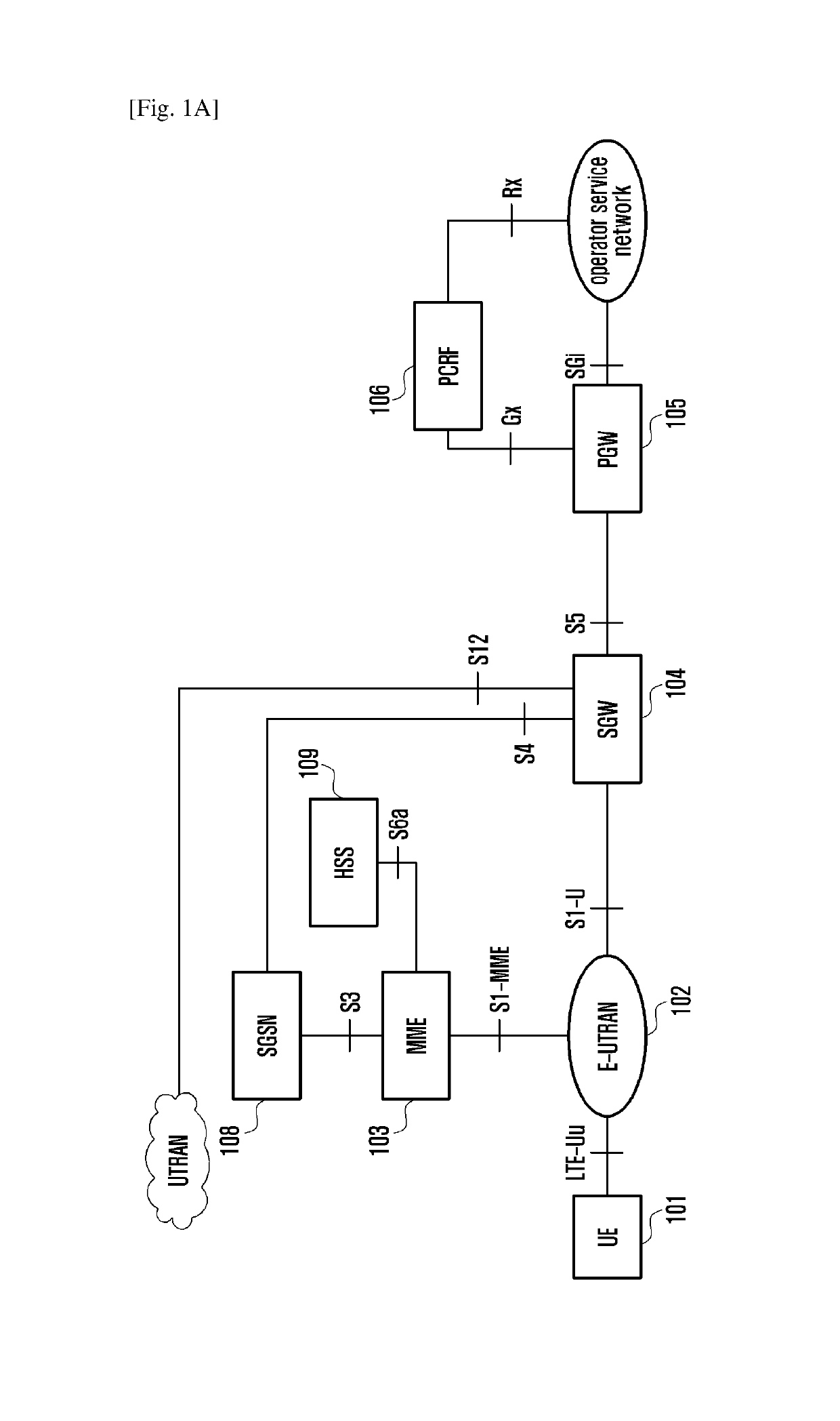
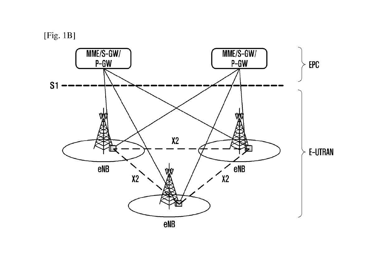
TECHNICAL FIELD[0001]The present disclosure relates to radio communication technologies, and more particularly to cache-based data transmission methods and apparatuses.BACKGROUND ART[0002]Mobile communication system now pays close attention to high-speed data services and user experiences. For example, both a Long Term Evolution (LTE) system corresponding to Evolved Universal Terrestrial Radio Access (E-UTRA) protocol specified by 3rd Generation Partnership Project (3GPP) and a LTE-Advanced system provide high-speed mobile data services. By means of Carrier Aggregation (CA) technology, the peak rate of the LTE-A system may exceed 1 Gbps. Moreover, through improving the architecture of the LTE system, the number of network nodes in the LTE-A system is reduced, and then end-to-end delay is improved. Accordingly, compared with the previous 3G systems, the LTE-A system may provide better user experiences.[0003]FIGS. 1A and 1B are diagrams illustrating the structure of System Architectur...

Claims


Application Information

Patent Timeline
Patent Type & Authority Patents(United States)
IPC IPC(8): H04W72/04H04L29/08
CPCH04L67/2842H04W72/044H04W76/14H04W28/14H04W28/0278H04L67/568
Inventor WANG, HONGXU, LIXIANGSUN, CHENGJUNYU, BIN
Owner SAMSUNG ELECTRONICS CO LTD
Why Eureka
Try Eureka