
Charging method and charging system

A charging method and charging system technology, applied in charging stations, charging/discharging current/voltage regulation, electric vehicle charging technology, etc., can solve problems such as battery deterioration acceleration, and achieve the effect of capacity deterioration suppression

Inactive Publication Date: 2013-05-08
TOYOTA JIDOSHA KK +1
View PDF6 Cites 1 Cited by
  • Summary
  • Abstract
  • Description
  • Claims
  • Application Information

AI Technical Summary

Problems solved by technology

[0004] However, the technique disclosed in Japanese Patent Application Laid-Open No. 2009-118652 has a problem that since the battery is kept in a fully charged state between the time when charging is completed and the designated time for charging completion, the deterioration of the secondary battery is accelerated.

Method used


Image

  • Charging method and charging system
  • Charging method and charging system
  • Charging method and charging system

Examples


Embodiment Construction

[0039] Embodiments of the present invention will be described in detail below with reference to the accompanying drawings.

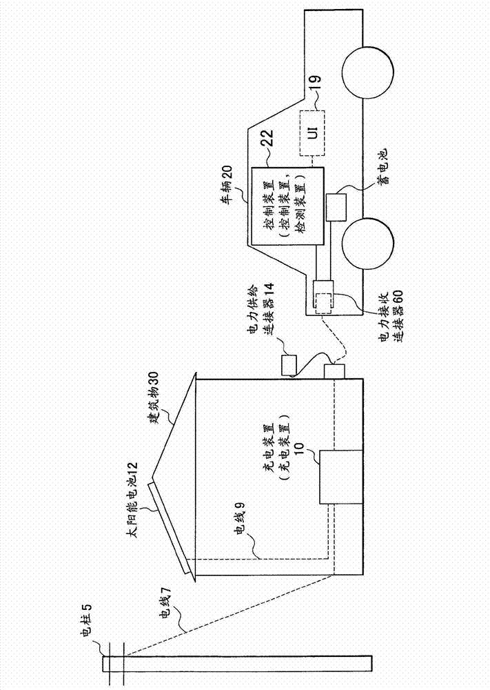
[0040] figure 1 A configuration including a charging system according to the invention is shown. The figure shows a utility pole 5 , electric wires 7 and 9 , a building 30 , a solar cell 12 , a charging device 10 , a power supply connector 14 , and a vehicle 20 .

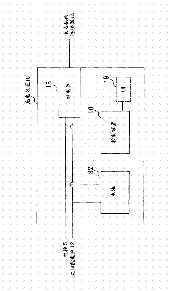
[0041]Among them, the electric column 5 supplies electric power from the electric power system. Electric power is supplied to the building 30 via the electrical line 7, in particular to the charging device 10 in this embodiment. The solar cell 12 converts light energy into electric power, and the electric power is supplied to the charging device 10 through the electric wire 9 . The power supply connector 14 supplies power to the vehicle 20 . The charging device 10 controls charging of a storage battery provided in the vehicle 20 . Details about the charging device 10 will be described lat...


PUM


Abstract

Use start date-and-time is input by use of U1. Times T1 and T2 to achieve SOC 1 and SOC 2 are set. Charging is started at T2 and is continued until it is determined that SOC 2 is achieved. Thereafter, charging is started at T1 and continued until it is determined that SOC 1 is achieved by the input use start date-and-time.

Description

technical field [0001] The present invention relates to a charging system and a charging method, particularly a charging system and a charging method for charging a secondary battery whose capacity deterioration is more accelerated as the state of charge becomes higher. Background technique [0002] Certain batteries, such as lithium-ion batteries, may experience accelerated capacity degradation when stored in a fully charged state. Lithium-ion batteries are installed in hybrid cars, electric vehicles, and the like. In these cases, the acceleration of capacity degradation may affect distance-to-empty, among other things. [0003] Japanese Patent Application Publication No. 2009-118652 discloses a charging technique for such an in-vehicle battery. This technique includes a communication relay device for communicably connecting an electric vehicle with a power server provided in a user's residence, so that a battery can be charged at a lower electricity price in the user's r...

Claims


Application Information

Patent Timeline
Patent Type & Authority Applications(China)
IPC IPC(8): B60L3/00B60L3/12B60L11/18
CPCY02T10/7044B60L11/1846Y02T10/7011B60L11/1816Y02T90/14Y02T90/121Y02T90/163Y04S30/14B60L11/1838B60L3/0046Y02T10/7005B60L11/1848B60L11/184Y02T10/7083B60L11/1862Y02T10/705Y02T10/7088Y02T90/169B60L3/12H02J7/007B60L8/003B60L2230/16Y02T90/128B60L53/14B60L53/60B60L53/64B60L53/65B60L53/665B60L58/13B60L53/305Y02T10/70Y02T10/7072Y02T90/167Y02T90/12Y02T90/16
Inventor 刀根川浩巳石川哲浩市川真士石井大祐村若亮宪
Owner TOYOTA JIDOSHA KK
Learn More