Piston for an internal combustion engine

A technology for internal combustion engines and pistons, applied to pistons, piston rings, cylindrical pistons, etc., can solve problems such as piston deformation

Active Publication Date: 2013-05-08
MAHLE INT GMBH
View PDF8 Cites 0 Cited by
  • Summary
  • Abstract
  • Description
  • Claims
  • Application Information

AI Technical Summary

Problems solved by technology

[0003] The problem with this type of box piston is that when operating in motor mode, the for...

Method used


Image

  • Piston for an internal combustion engine
  • Piston for an internal combustion engine
  • Piston for an internal combustion engine

Examples


Embodiment Construction

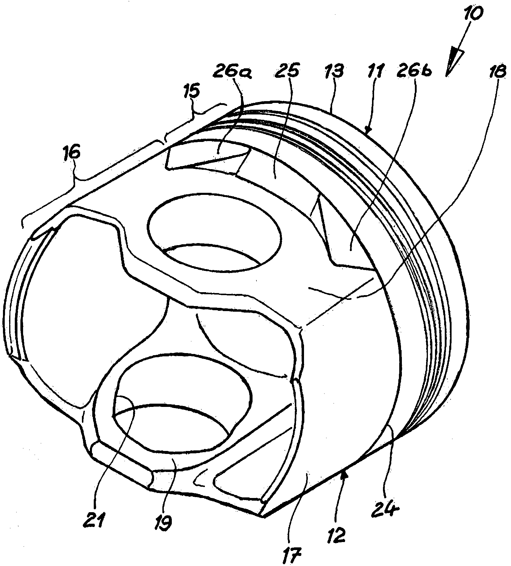
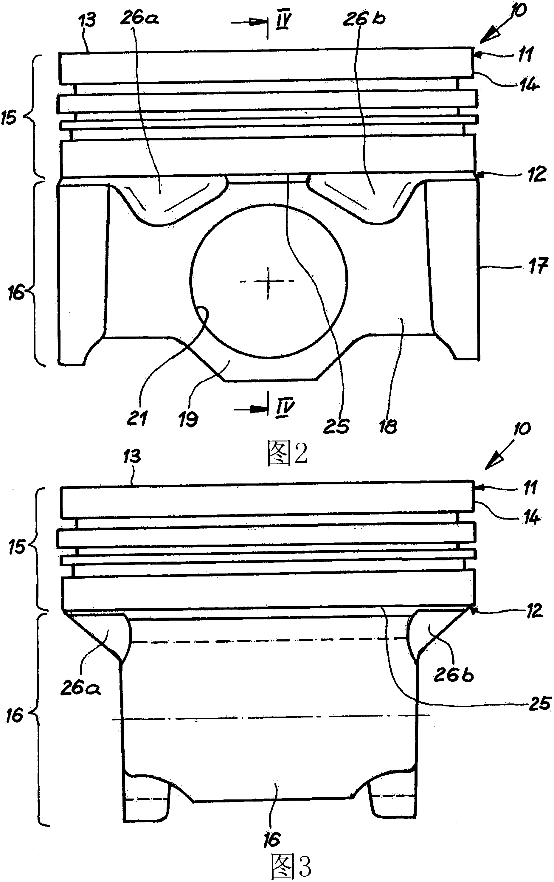
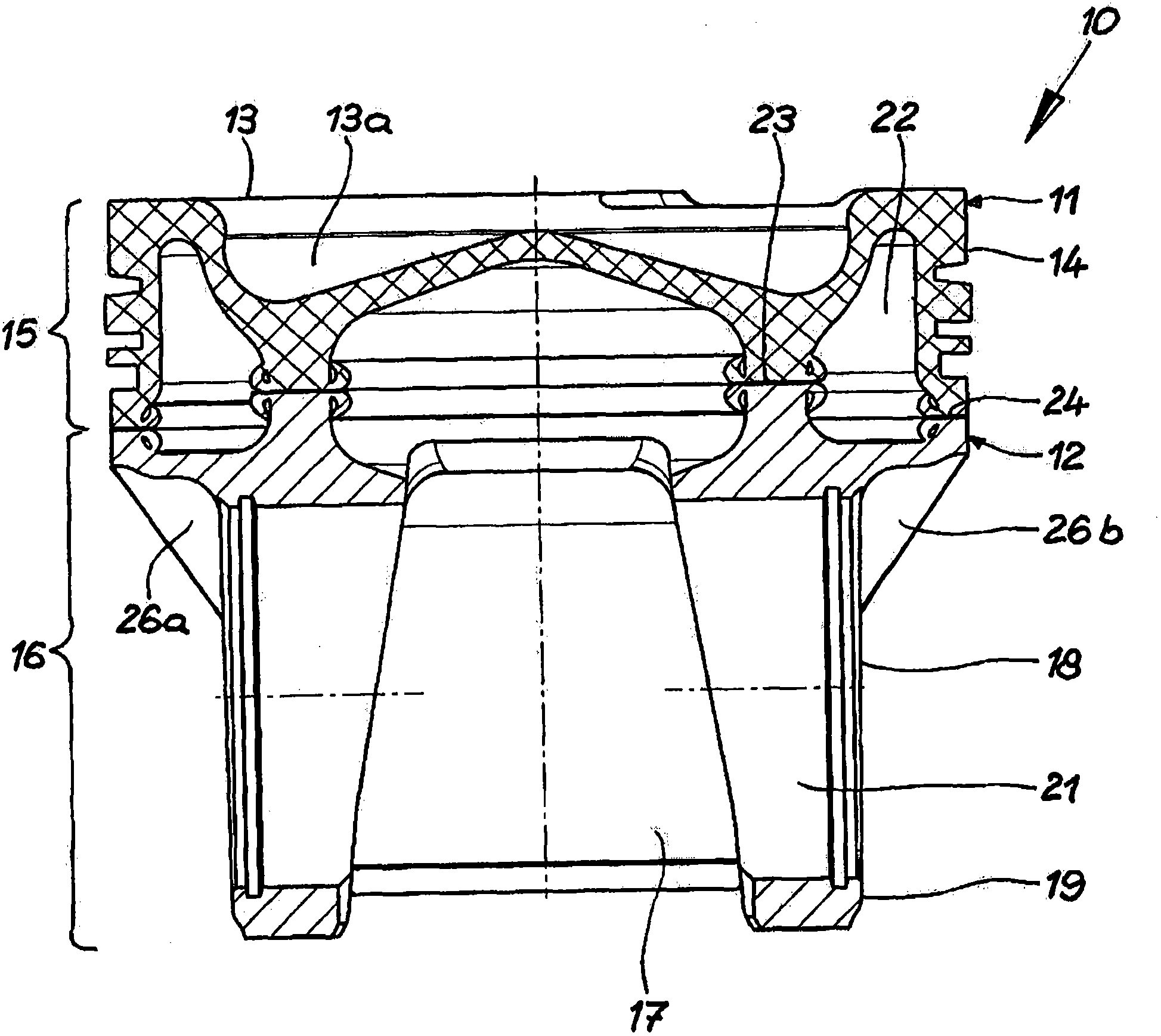
[0021] Figure 1 to Figure 4 This is an embodiment of the piston 10 provided by the present invention. In this embodiment, the piston is made of steel. In this embodiment, the piston 10 provided by the present invention is composed of two parts. It is composed of a piston top 11 and a piston bottom 12. The piston top 11 has a piston head 13 containing a basin-shaped combustion chamber 13a and a surrounding annular section 15 containing a fire bank 14. The piston bottom 12 has a piston skirt 16 engaged with the bottom surface of the piston head 13. The piston skirt 16 has two skirt walls 17 and two box walls 18 connected to the skirt walls 17 and recessed relative to the ring section 15. This forms the unsupported bottom surface 25 of the ring section 15. The outer peripheral surface of each skirt wall 17 constitutes a working surface of the piston skirt 16. Each box wall 18 has a pin hub 19 provided with a hub hole 21.

[0022] The piston top 11 and the piston bottom 12 for...


PUM


Abstract

The present invention relates to a piston (10) for an internal combustion engine, comprising a piston crown (13), a circumferential fire land (14), a circumferential ring part (15) having annular grooves, and a piston skirt (16), which comprises two skirt walls (17) and two box walls (18) set back from the ring part (15) and connecting the skirt walls (17) in such a way that an exposed underside (25) of the ring part (15) is formed in the area of each of the box walls (18), wherein the box walls (18) are provided with pin bosses (19) having pin bores (21). According to the invention, at least one support element (26a, 26b) is arranged between each exposed underside (25) of the ring part (15) and the box wall (18) associated with said underside of the ring part.

Description

Technical field [0001] The present invention relates to a piston for an internal combustion engine, comprising a piston head, a surrounding firepower bank, a surrounding annular section with an annular groove, and a piston skirt. The piston skirt has two skirt walls and two skirt walls connecting the skirt walls. An unsupported bottom surface of the ring segment is formed in each area of ​​the ring segment relative to the concave box wall of the ring segment, wherein a pin hub with a hub hole is provided on the box wall. Background technique [0002] The same type of piston is disclosed from the international patent application WO 2008 / 128611 A1. Pistons with this structure are also called box pistons. The two oppositely arranged walls of the piston skirt of a conventional box-type piston are concave with respect to the outer contour of the piston. The concave wall is called the box wall, and the other two non-concave walls are skirt walls and contain the real working surface o...

Claims


Application Information

Patent Timeline
IPC IPC(8): F02F3/00
CPCF02F3/00F02F3/0076F16J1/00F16J9/00
Inventor W·依斯勒P·肯尼茨
Owner MAHLE INT GMBH
Why Eureka
Try Eureka