Wind turbine blade with narrow shoulder and relatively thick airfoil profiles

A technology of wind turbine and relative thickness, which is applied to wind turbines, wind turbines, motors, etc., which are consistent with the wind direction, can solve the problem that the blades of the wind turbine model cannot be replaced, and achieve the effect of reducing storm load and low trailing edge curvature.

Active Publication Date: 2013-05-08
LM GLASSFIBER
View PDF5 Cites 16 Cited by
  • Summary
  • Abstract
  • Description
  • Claims
  • Application Information

AI Technical Summary

Problems solved by technology

However, the blades of a wind turbine model cannot b

Method used


Image

  • Wind turbine blade with narrow shoulder and relatively thick airfoil profiles
  • Wind turbine blade with narrow shoulder and relatively thick airfoil profiles
  • Wind turbine blade with narrow shoulder and relatively thick airfoil profiles

Examples


example

[0076] Examples of wind turbine blades according to the invention are given below.

[0077] A wind turbine blade is provided with the following parameters regarding length, shoulder width, minimum radius of curvature for the trailing edge and root cylinder diameter:

[0078] parameter size L 42.13m L w 8.5m W 2.975m r o 10.3m r i 11.3m D 1.893m

[0079] Table 1

[0080] Chord length c, relative thickness t / c, and pre-bending Δy The distribution of is listed in Table 2:

[0081]

[0082] Table 2

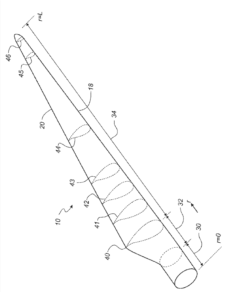
[0083] The wind turbine blade comprises six novel blade profiles 41-46 located at different longitudinal positions along the blade and such as figure 2 shown. Table 3 lists the relative thickness t / c of ​​the profile and the position d of the maximum thickness t / c, position d of maximum pressure side camber p / c and approximate radial position r:

[0084] airfoil reference mark t / c d t / c d p / c r ...


PUM


Abstract

A blade (10) for a rotor of a wind turbine having a profiled contour divided into: a root region (30), an airfoil region (34), and a transition region (32) between the root region (30) and the airfoil region (34). A shoulder (40) is located at the boundary between the transition region (32) and the airfoil region (34). The blade's profiled contour comprises a local relative thickness defined as the local ratio between a maximum profile thickness (t) and the chord length (c). The ratio between the shoulder width (W) and the blade length (L) being less than or equal to 0.075, and the relative thickness (t/c) in a blade length interval of 0-0.8L is at least 22%.

Description

technical field [0001] The invention relates to a blade for a rotor of a wind turbine having a substantially horizontal rotor shaft, said rotor comprising a hub from which the blade extends substantially in a radial direction when fitted to the hub, the blade having a transverse direction and having a tip end and In the longitudinal direction of the root end, the blade further comprises: a profiled profile comprising a pressure side and a suction side, and a leading edge and a trailing edge with a chord having a chord length extending between the leading edge and the trailing edge, the profiled profile being Lift is generated upon impingement by an incident airflow, wherein the profile is divided into: a root region with a substantially circular or elliptical profile closest to the hub, an airfoil region with a lift-generating profile furthest from the hub, and a root region with A transition region between airfoil regions having a profile that changes gradually in radial dire...

Claims


Application Information

Patent Timeline
IPC IPC(8): F03D1/06
CPCF05B2250/71F03D1/0633F05B2250/62F05B2240/301Y02E10/721F03D1/0641Y02E10/72
Inventor J.马德森C.F.安德森P.福格桑
Owner LM GLASSFIBER
Why Eureka
Try Eureka