Mounting frame and support of photovoltaic components and mounting method thereof

A photovoltaic module and support frame technology, which is applied to the support structure of photovoltaic modules, photovoltaic power generation, photovoltaic modules, etc., can solve the problems of low annual power generation, low total solar radiation, and high installation labor intensity, and reduce labor intensity. ,Easy to disassemble, improve the effect of annual power generation

Inactive Publication Date: 2014-12-17
ZHEJIANG JINKO SOLAR CO LTD +1
View PDF4 Cites 3 Cited by
  • Summary
  • Abstract
  • Description
  • Claims
  • Application Information

AI Technical Summary

Problems solved by technology

With this installation method, the assembly and fixation of the bracket and the installation of the module are carried out in two steps, so the overall installation labor intensity is high; in addition, since the installation tilt angle cannot be changed after the support frame is fixed, the photovoltaic module can only be installed with The fixed tilt angle faces the sun to collect solar radiation, which will make its annual power generation lower
Because the power generation efficiency of photovoltaic modules can reach the highest when the sunlight directly shines on the photovoltaic modules, and for most regions, the solar altitude angle is very different in summer and winter in a year, and installing modules at a single fixed inclination angle will cause other The total annual solar radiation collected is low, resulting in a low annual energy production

Method used


Image

  • Mounting frame and support of photovoltaic components and mounting method thereof
  • Mounting frame and support of photovoltaic components and mounting method thereof
  • Mounting frame and support of photovoltaic components and mounting method thereof

Examples


Embodiment 1

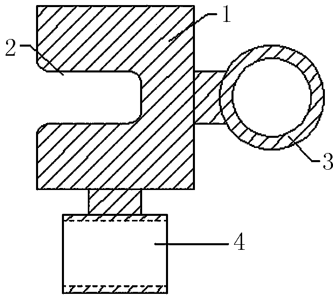
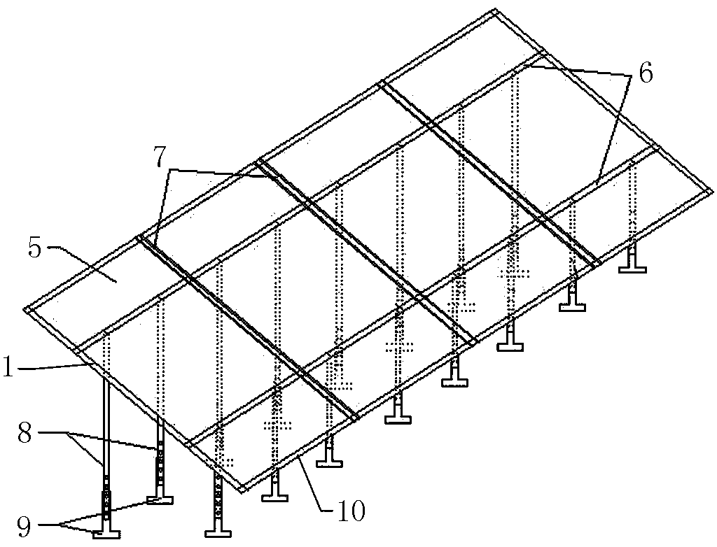
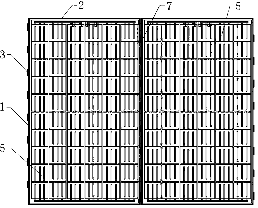
[0024] Embodiment 1: as attached figure 1 , figure 2 , image 3 As shown, a photovoltaic module installation frame, the installation frame includes a long frame body 1, a short frame body 10, a beam 6, and a slanted beam 7, wherein the side of the long frame body 1 is provided with a card slot I2 for installing a photovoltaic module 5, The other side is provided with some inclined beam connecting cylinders 3 matched with the inclined beams 7, and two crossbeam connecting cylinders 4 matched with the crossbeams 6 are respectively arranged at both ends of the bottom of the long frame main body 1; There is a card slot II11 for installing the photovoltaic module 5; the crossbeam 6 and the inclined beam 7 are respectively provided with a nut 12 at one end and a thread 13 at the other end, wherein the crossbeam 6 matches the length of the main body 1 of the long frame, and the inclined beam 7 and the short The bezel body 10 is matched in length. The beam 6 is connected with the ...

Embodiment 2

[0025] Embodiment 2: as attached Figure 4 , Figure 5 As shown, a photovoltaic module installation support frame, the support frame includes a support rod 8 and a support foot 9, the upper end of the support rod 8 is provided with a connecting cylinder 14, the inner diameter of the connecting cylinder 14 matches the outer diameter of the beam 6, and is used to match the The beam 6 is connected; the supporting foot 9 includes a connecting rod 15 and a chassis 16, the upper part of the connecting rod 15 is hollow, the inner diameter of the hollow part matches the outer diameter of the supporting rod 8, and the lower part of the supporting rod 8 and the upper part of the supporting foot 9 Threaded holes 17 with the same diameter are respectively provided, among which five are provided at the lower part of the supporting rod 8, and three are provided at the upper part of the connecting rod 15, and the supporting rod 8 and the connecting rod 15 are fixedly connected by bolts. Two...

Embodiment 3

[0026] Embodiment 3: as attached Figure 6 , Figure 7 As shown, an installation method for installing photovoltaic modules using the above-mentioned installation frame and installation support frame is as follows:

[0027] Step 1: Fix the front and rear rows of support feet 9 on the installation site through the installation holes 18 with bolts;

[0028] Step 2: Adjust the required installation angle of the photovoltaic module as needed, that is, by adjusting the connection positions of the front and rear rows of support rods 8 and the threaded holes 17 of the connecting rod 15, and then use bolts to fix the front and rear rows of support feet 9 and the support rods 8 connect;

[0029] The third step: use two beams 6, from left to right or from right to left, connect the front and back rows of support rods 8 in turn through the connecting cylinder 14 at the upper end of the support rods 8;

[0030] Step 4: Insert each group of photovoltaic modules 5 into the card slots I2 ...


PUM


Abstract

The invention discloses a mounting frame and a support of photovoltaic components and a mounting method thereof. Required mounting angles of the photovoltaic components are adjusted by adjusting threaded hole connecting positions of support rods and connecting rods in the front and rear rows, two crossbeams penetrate connecting barrels at the upper end of the support rods from left to right or from right to left so as to sequentially connect the support rods in the front and rear rows, the photovoltaic components are fastened in first fastening grooves of a long frame body and second fastening grooves of a short frame body respectively and are adhered by silica gel; the two adjacent photovoltaic components are connected to each other via cant beams; the crossbeams are connected with two crossbeam connecting barrels at two ends of the bottom of the long frame body, and after the photovoltaic components are assembled, the photovoltaic components are fixedly connected with the threaded ends of the crossbeams and the cant beams via nuts. The mounting frame has high mechanical strength and stability, long-term and reliable running of the integral photovoltaic system can be guaranteed; mounting and detachment are facilitated, inclined mounting angles of the photovoltaic components can be adjusted at any time according to solar irradiance of seasonal variation, and accordingly, annual energy output of the photovoltaic components is increased.

Description

technical field [0001] The invention relates to a photovoltaic module, in particular to a photovoltaic module installation frame, a support frame and an installation method thereof. Background technique [0002] At present, the common photovoltaic module is rectangular in shape, and its structure from top to bottom is glass, encapsulation film, battery sheet, encapsulation film and back plate, and there are frames around it to enhance its mechanical strength and facilitate installation. In order to provide stable power supply for photovoltaic modules, they need to be installed and integrated into a photovoltaic system. Common photovoltaic systems include roof photovoltaic systems, photovoltaic curtain walls, and ground photovoltaic power plants. At present, photovoltaic modules in most photovoltaic systems are installed in a fixed way. The installation method is to first assemble and fix the photovoltaic support at a preset inclination angle, and then fix the frame of the p...

Claims


Application Information

Patent Timeline
Patent Type & Authority Applications(China)
IPC IPC(8): H02S20/10H02S20/20H02S20/23
CPCY02B10/10Y02E10/50
Inventor 刘俊辉金浩刘亚锋刘增胜
Owner ZHEJIANG JINKO SOLAR CO LTD
Why Eureka
Try Eureka