Artificial airflow power generating method and artificial airflow power generating system

A power generation system and air flow technology, applied in the field of wind power generation, can solve the problems of construction difficulty and high cost, unseen investment scale promotion and commercial operation, etc.

Inactive Publication Date: 2012-04-18
夏卫平
View PDF6 Cites 3 Cited by
  • Summary
  • Abstract
  • Description
  • Claims
  • Application Information

AI Technical Summary

Problems solved by technology

Therefore, although the experiment in Spain mentioned above achieved successful power generation, due to the difficulty and high cost of building such a high column, this type of scheme has not been put into scale promotion and commercial operation.

Method used


Image

  • Artificial airflow power generating method and artificial airflow power generating system
  • Artificial airflow power generating method and artificial airflow power generating system
  • Artificial airflow power generating method and artificial airflow power generating system

Examples


Embodiment 1

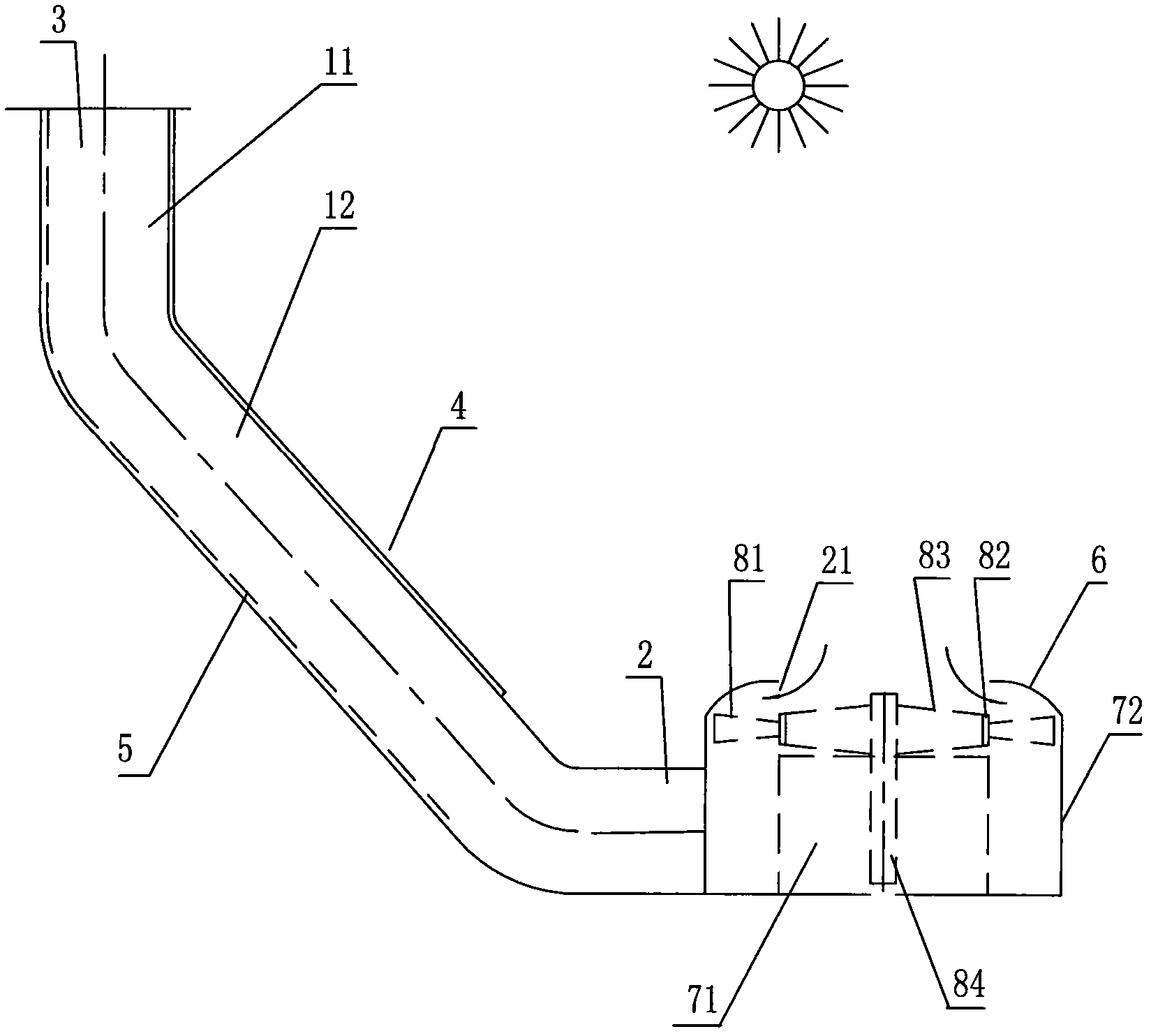
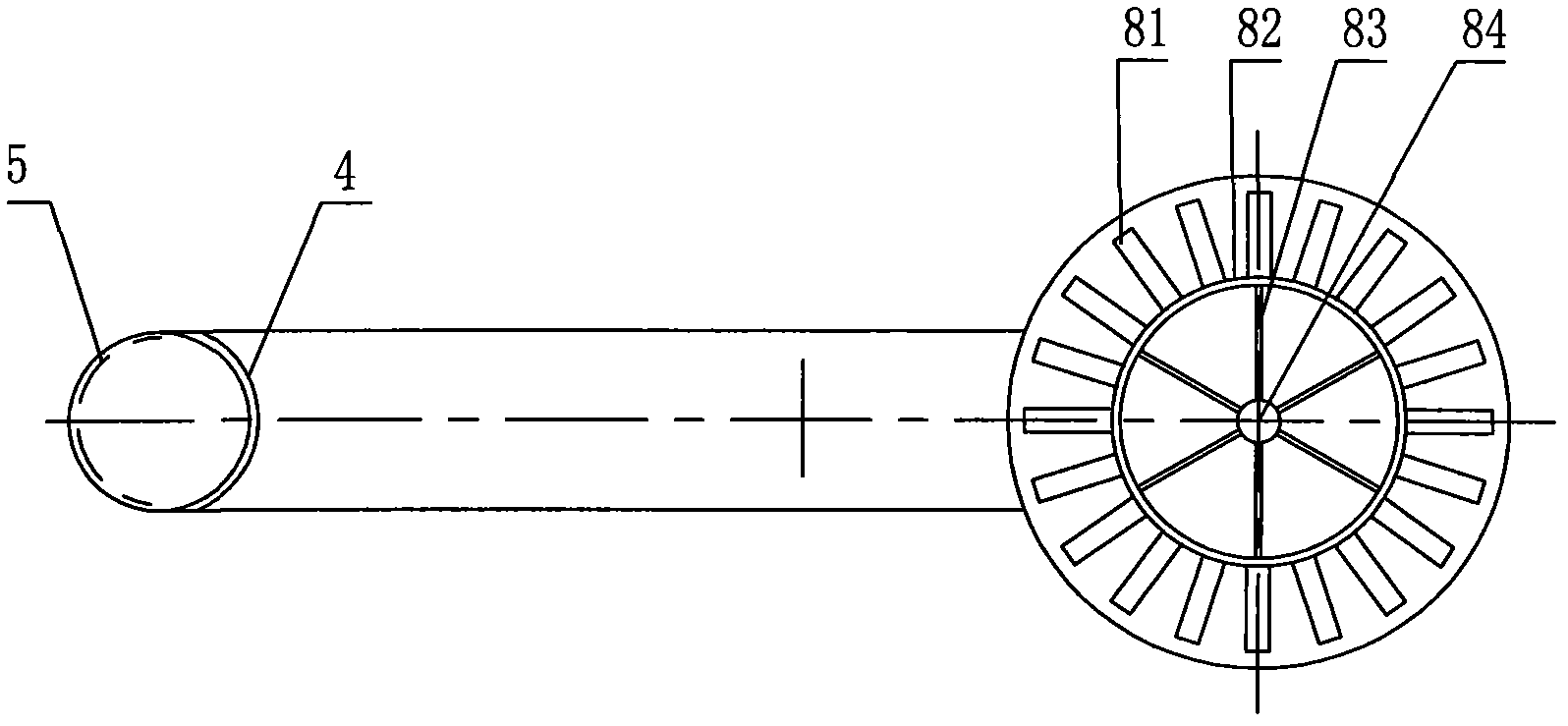
[0058] figure 1 It is a principle schematic diagram of an embodiment of the method and system for generating electricity by artificial airflow of the present invention. figure 2 yes figure 1 top view.

[0059] As shown in the figure, the artificial air flow power generation system of this embodiment is composed of a cylinder on the left side of the figure and a device for converting airflow energy into mechanical energy and electrical energy on the right side of the figure. As shown in the figure, the device that converts airflow energy into mechanical energy and electrical energy includes a figure 1 The upper airflow energy-mechanical energy conversion unit and the figure 1 The lower mechanical energy-electrical energy conversion unit 71;

[0060] The airflow energy-mechanical energy conversion unit can adopt a wheel-shaped wind impeller. This wheel-shaped wind impeller is made up of blade 81, rim 82, spoke 83 and power take-off shaft 84, as figure 1 and figure 2 , t...

Embodiment 2

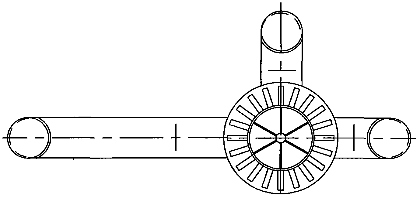
[0066]The method and system of the artificial air flow power generation in this embodiment are basically the same as in Embodiment 1, the difference is that: on the outer periphery of the air flow energy-mechanical energy conversion unit, in Embodiment 1 there is only one connected with two single cylinders A column string formed in series, and this embodiment is provided with a column group consisting of multiple single columns and / or column strings ( image 3 Only three of them are shown). The air inlets of each single column and column string of the column group are in communication with the annular air inlet 72 .

[0067] For a column group composed of 10 single columns (the diameter of the air outlet of each single column is 10 meters), the cross-sectional area of ​​the total air inlet of the system is taken as 1 / 10 of the total cross-sectional area of ​​the final air outlet. Assuming that the air inlet temperature is 25°C, the air outlet temperature is 35-50°C, and the ...

Embodiment 3

[0071] Figure 4 It is a structural schematic diagram of another embodiment of the method and system for generating electricity by artificial airflow of the present invention. As shown in the figure, the artificial air flow power generation system of this embodiment includes a cylinder 1 built on a horizontal plane. The cylinder can be a hollow full concrete cylinder. An air inlet 2 is arranged above the cylinder. There is an air outlet 3. The upper part of the cylinder 1 is provided with a device 7 that can convert airflow energy into mechanical energy and electrical energy. The device 7 that converts airflow energy into mechanical energy and electric energy has a fan blade 81 driven by airflow; below the fan blade 81, a spray head group 9 is provided; the spray head group 9 passes through a pipeline and a water pump 10 Connection to surface or ground water, or deep sea cold water sources. The cold water introduction and spray formation unit composed of the spray head grou...


PUM


Abstract

The invention discloses an artificial airflow power generating method and an artificial airflow power generating system. The system comprises a column casing of which the two ends are provided with an air inlet and an air outlet, wherein the column casing is a single column casing, a string of column casings or a column casing group consisting of multiple column casings which share one air inlet; the column casing group is provided with one or multiple shared air outlets; the room-temperature air naturally absorbed into the column casing from the air inlet is heated, cooled or heated firstly and then cooled in the column casing; a passage through which airflow positioned at the air inlet flows into the column casing or an airflow passage which is between the air inlet and the air outlet and is adjacent to one side of the air inlet is provided with a device capable of converting airflow energy into mechanical energy and electric energy; and driven by the airflow naturally absorbed into the column casing, the device realizes power generation. The method and corresponding system disclosed by the invention are wide in application range and lower in cost and are suitable for being applied to industrial production and commercial operation. The invention also discloses a wheel-shaped wind impeller which has extremely high airflow energy-mechanical energy conversion efficiency and can be matched with the method and the system for use.

Description

technical field [0001] The invention relates to the field of wind power generation, and more specifically relates to a method for generating electricity by artificial air flow and a system for generating electricity by artificial air flow. Background technique [0002] With the increasing demand for electric energy, electric energy has become the most important source of power for human production and living activities. However, the excessive use of fuel to generate electricity has made the climate abnormal. If things go on like this, human beings will have to face the revenge of nature, and will pay an increasingly heavy price. [0003] There are many known and inexhaustible sources of energy in nature. How to develop and utilize these energy sources more easily and in a friendly and friendly way with nature is the direction that human beings have been striving for. [0004] As we all know, wind is flowing air, that is, air flow, which is formed due to the heating or coo...

Claims


Application Information

Patent Timeline
Patent Type & Authority Applications(China)
IPC IPC(8): F03D9/00F03D11/00F24J2/05F24J2/48F03D9/25F03D9/37F24S10/40
CPCY02E10/44Y02E10/722Y02E10/72Y02P70/50
Inventor 夏卫平
Owner 夏卫平
Why Eureka
Try Eureka