Connecting-rod-type bending device for bending steel in steel forming machine

A technology for bending steel bars and bending devices, which is applied in the field of link-type bending devices, can solve the problems of steel bar bending accuracy affecting the working efficiency of steel bar forming machines, difficulty in feeding and retrieving steel bars, and low bending accuracy of steel bars, etc., to achieve High bending accuracy, easy to put and take out materials, and easy to take out materials

Active Publication Date: 2013-05-15
冯广建
View PDF6 Cites 4 Cited by
  • Summary
  • Abstract
  • Description
  • Claims
  • Application Information

AI Technical Summary

Problems solved by technology

After the reinforcement is placed in the space between the hinge pin and the positioning pin, there will be a certain gap margin. The size of the margin directly affects the working efficiency of the steel bar forming machine and the bending accuracy of the steel bar. When there is no margin or the margin is small, Then the steel bar is in close contact with the hinge pin and positioning pin, and the bending accuracy is high, but it is difficult to discharge and take out the steel bar, and the work efficiency is low; when the margin is large, the distance between the steel bar and the hinge pin and positioning pin is relatively large. It is convenient for discharging and retrieving materials, but the bending accuracy of steel bars is low
However, the distance between the hinge pin and the positioning pin of the above-mentioned swing bending mechanism is determined, which cannot meet the requirements of high work efficiency and high bending accuracy at the same time. It is usually used for bending steel bars of a certain specification. Take the balance point between them. When bending steel bars of other specifications, it is easy to cause difficulty in discharging and retrieving materials or low bending accuracy.

Method used


Image

  • Connecting-rod-type bending device for bending steel in steel forming machine
  • Connecting-rod-type bending device for bending steel in steel forming machine
  • Connecting-rod-type bending device for bending steel in steel forming machine

Examples


Embodiment Construction

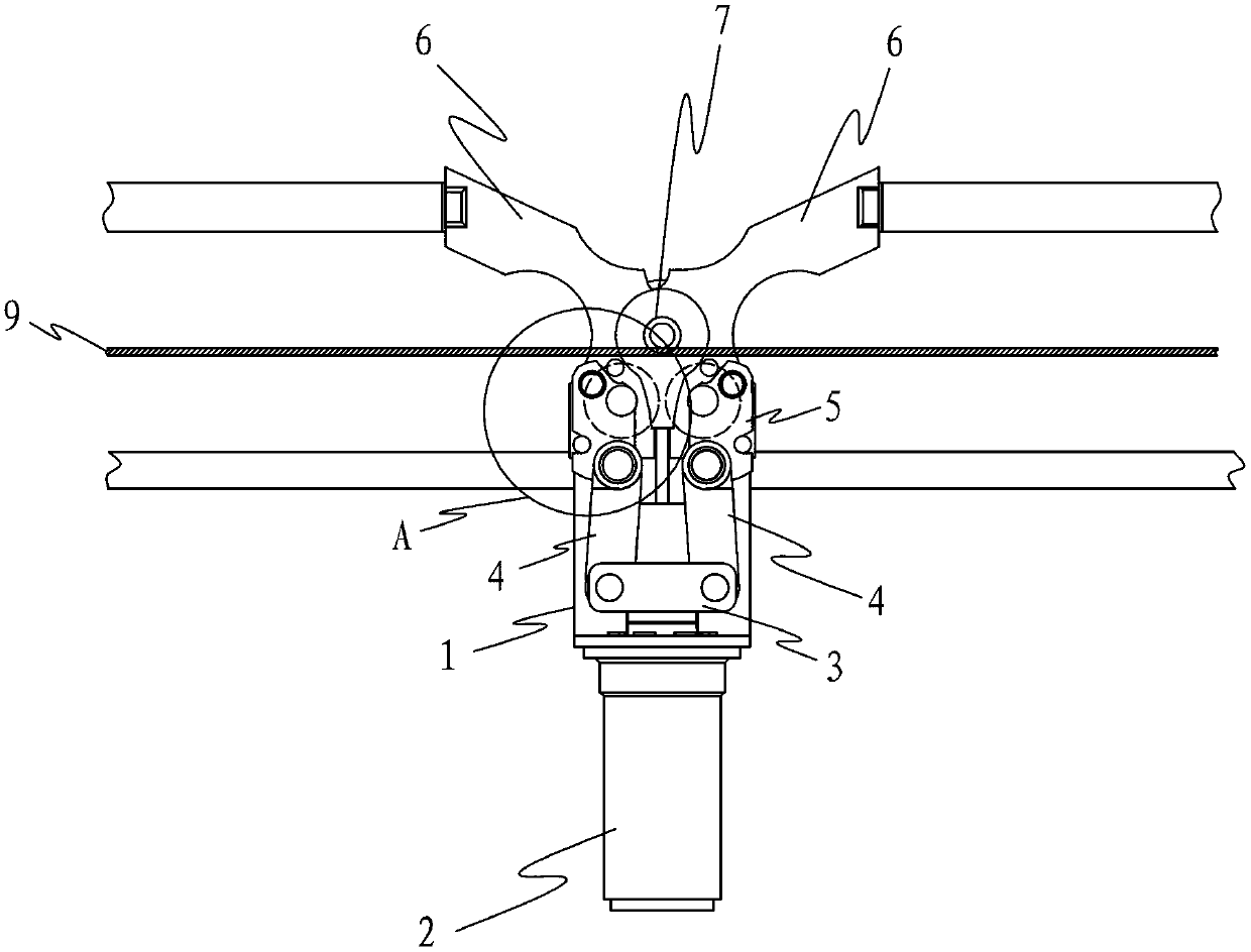
[0021] Such as figure 1 As shown, the present invention provides a connecting rod type bending device for bending steel bars of a steel bar forming machine, which includes a base 1 on which an oil cylinder 2, a push rod 3, a connecting rod 4, and a pin shaft thrust Seat 5, hinge plate 6 and hinge pin 7, wherein connecting rod 4, pin thrust seat 5, hinge plate 6 are respectively provided with two, and are symmetrically distributed on both sides of hinge pin 7. The push rod 3 is connected with the oil cylinder 2, and the two connecting rods 4 are respectively hinged at the two ends of the push rod 3, and the connecting rod 4, the pin shaft thrust seat 5 and the hinge plate 6 which are located on the same side of the hinge pin 7 are hinged sequentially, and the two A hinge plate 6 is hinged on the base 1 through a hinge pin 7 .

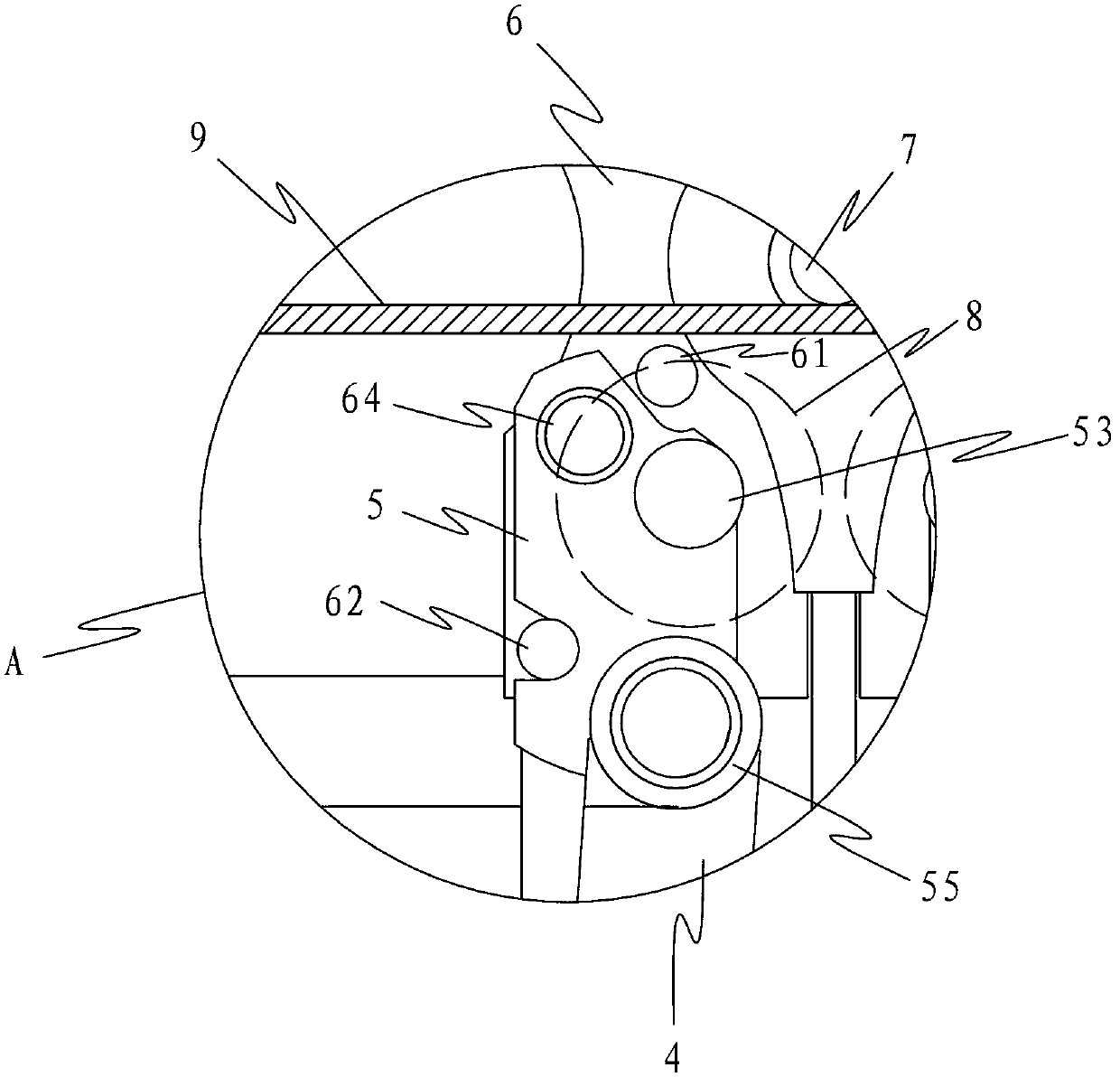
[0022] refer to Figure 5 , Figure 6 , Figure 5 Shown is a schematic structural view of the hinge plate 6, the hinge plate 6 is provided with an i...


PUM


Abstract

The invention discloses a connecting-rod-type bending device for bending steel in a steel forming machine. The connecting-rod-type bending device for bending the steel in the steel forming machine comprises a hinged pin shaft, a locating pin, a push rod, a connecting rod, a pin shaft thrust base and a hinged plate. The push rod, the connecting rod, the pin shaft thrust base and the hinged plate are sequentially connected in a hinged mode. The hinged plate is provided with an inner limiting pin which is used for limiting the inner rotation distance of the pin shaft thrust base and an outer limiting pin which is used for limiting the external rotation distance of the pin shaft thrust base. An inner clamping part and an outer clamping part are correspondingly arranged on the pin shaft thrust base. A location pin is arranged on the pin shaft thrust base. When steel is bent, the locating pin is pushed by the pin shaft thrust base to move forward a certain distance and matched with the hinged pin shaft to tightly press the steel, and the inner limiting pin is enabled to reach the inner clamping part. The pin shaft thrust base is stressed to move forward and the hinged plate is driven to swing. At the same time, the locating pin rotates around the hinged pin shaft to bend the steel. The connecting-rod-type bending device for bending the steel in the steel forming machine has the advantages that the distance between the hinged pin shaft and the locating pin can be changed when the steel is bent, and requirements for high working efficiency and high bending accuracy are simultaneously met when the steel is bent.

Description

technical field [0001] The invention relates to an accessory of a steel bar bending machine in the technical field of construction, in particular to a connecting rod type bending device used for a steel bar forming machine to bend steel bars. Background technique [0002] Various steel bars are often used in construction projects. The stirrup is also a kind of steel bar. It is mainly used to fix the position of the main steel bar and make the various steel bars inside the building components form a steel skeleton. The stirrups used in construction have various shapes. It is widely used, and the most common one is the stirrup skeleton frame that is bent into a rectangle by straight steel bars. The stirrup skeleton frame has five corners. Usually, two corners need to be bent first, and then turned around. For the two corners at the other end, the last corner is manually bent in the middle of the steel bar, and a total of five bending processes are performed to bend the steel b...

Claims


Application Information

Patent Timeline
Patent Type & Authority Applications(China)
IPC IPC(8): B21F1/00
Inventor 冯广建
Owner 冯广建
Why Eureka
Try Eureka