Numerical-control cutting machine combined with water jet scalpel and dicing saw

A technology of water cutting machine and cutting saw, applied in other manufacturing equipment/tools, metal processing, manufacturing tools, etc., can solve the problems of slow water cutting speed, not as fast as speed, not suitable for cutting curves, etc., and achieve the effect of high production efficiency

Inactive Publication Date: 2013-05-15
沈阳奥拓福科技股份有限公司
View PDF5 Cites 6 Cited by
  • Summary
  • Abstract
  • Description
  • Claims
  • Application Information

AI Technical Summary

Problems solved by technology

[0002] Waterjet cutting is widely used for its high efficiency, smooth cutting surface, small thermal deformation and suitable for cutting various shapes. The current CNC waterjet cutting machine can meet the processing requirements of special and complex geometric shapes. It has no cutting direction restrictions and can complete various Cutting with different curvature radii, and the radian size is accurate, no deformation, no further processing is required, but the speed of water cutting in straight line cutting is slower, far inferior to the speed of cutting straight lines with cutting saws, which is not conducive to the improvement of production efficiency
Although the cutting saw has the advantage of cutting straight lines, it is not suitable for cutting curves. Therefore, it is necessary to develop a cutting machine that can achieve precise cutting of the curvature radius of curves and fast straight cutting with the help of water jets and high-speed straight sawing performance.

Method used


Image

  • Numerical-control cutting machine combined with water jet scalpel and dicing saw
  • Numerical-control cutting machine combined with water jet scalpel and dicing saw
  • Numerical-control cutting machine combined with water jet scalpel and dicing saw

Examples


Embodiment Construction

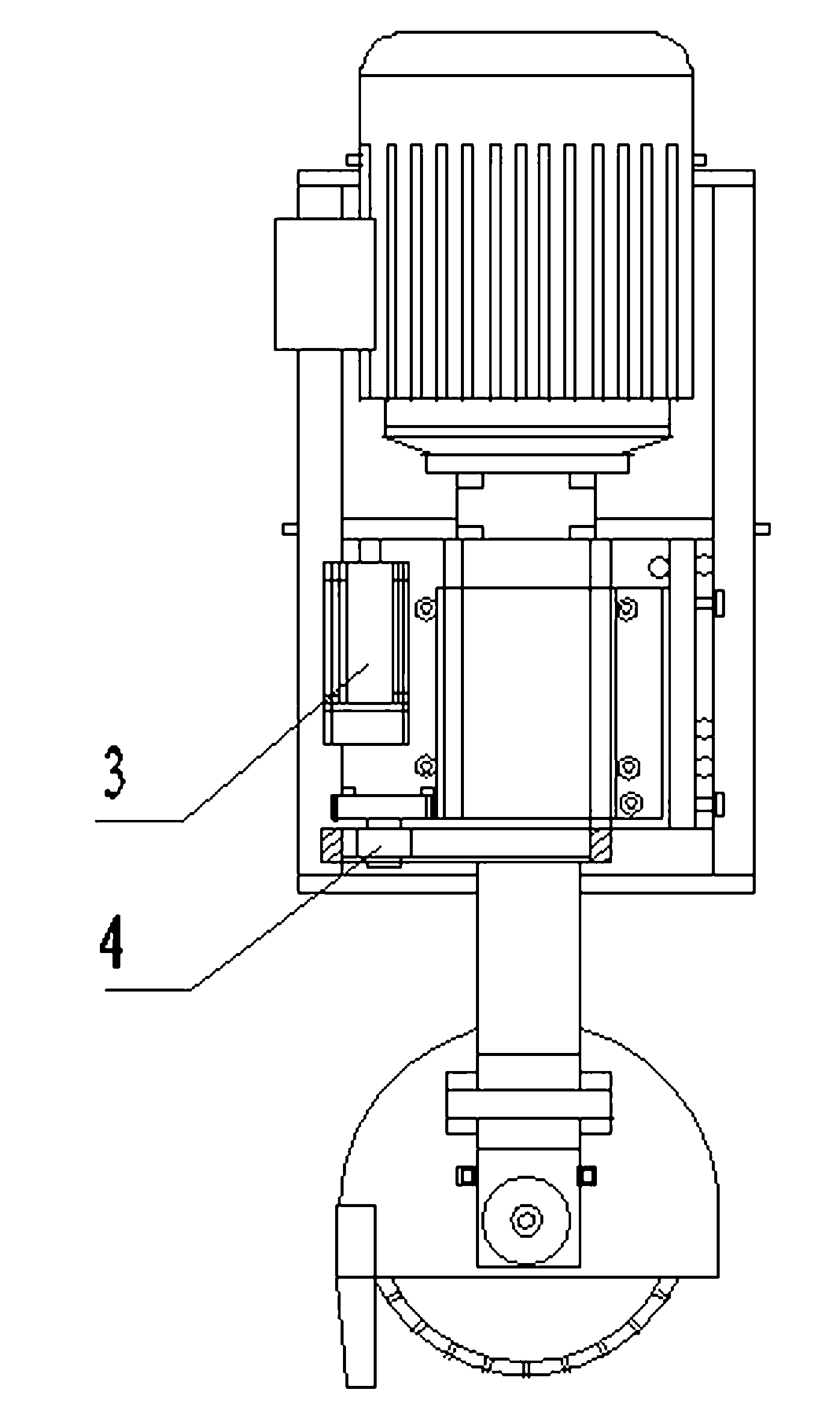
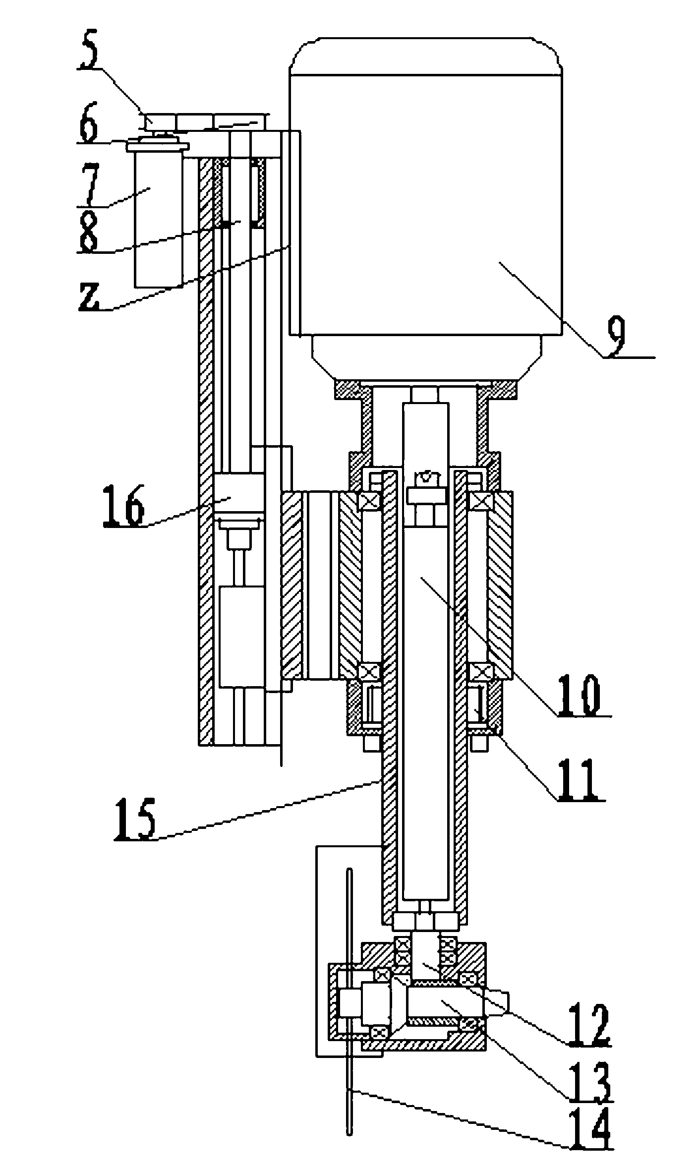
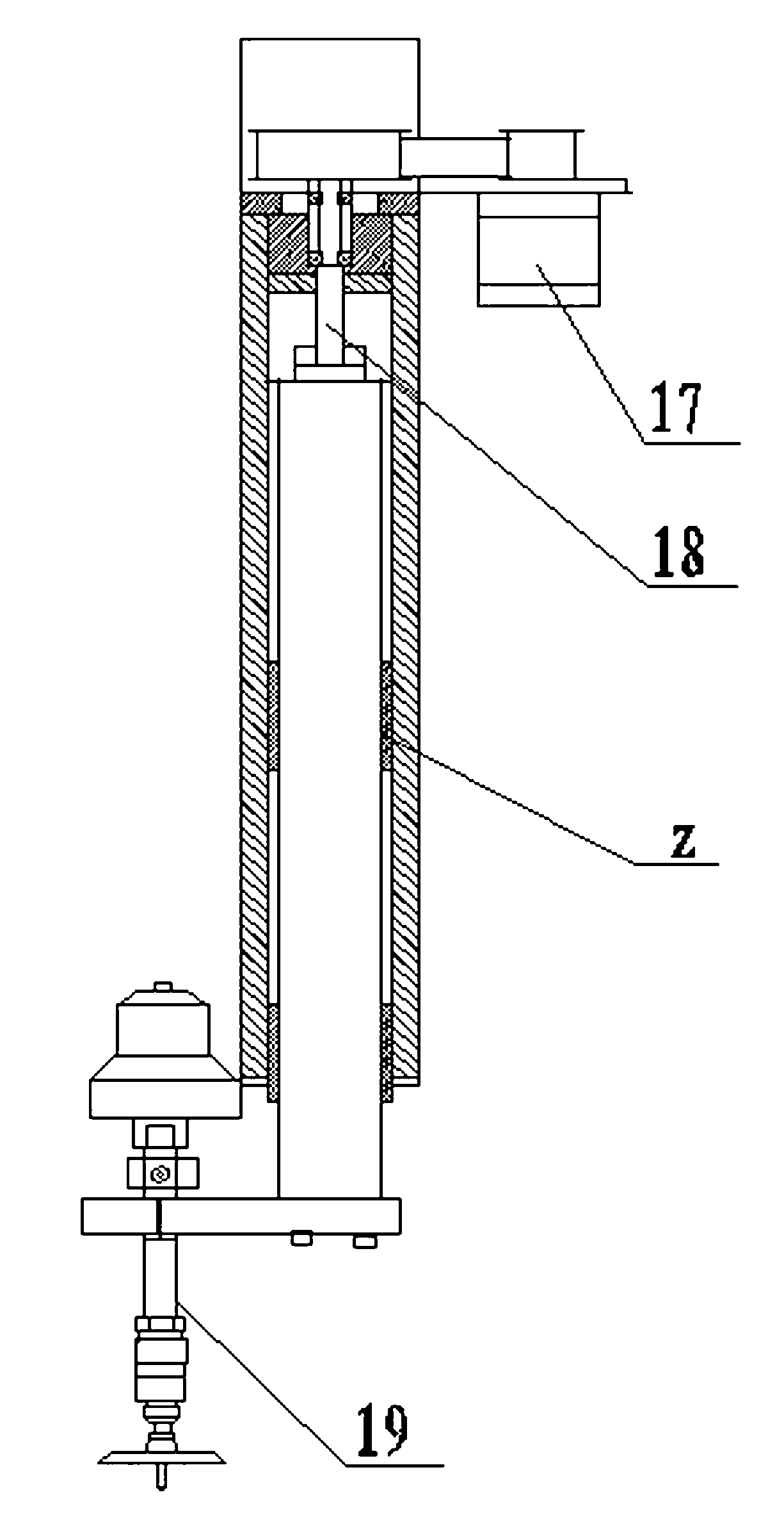
[0011] CNC cutting machine combined with water jet and cutting saw, including X axis of CNC water cutting machine, Y axis of CNC water cutting machine, water cutting device 2 set on the X axis of CNC water cutting machine, which can be lifted along the Z axis of water jet, can move along the cutting saw Z-axis lifting saw device 1. The cutting saw device is composed of a cutting saw Z-axis lifting transmission mechanism, a cutting saw driving mechanism and a cutting saw rotation transmission mechanism. The cutting saw Z-axis lifting transmission mechanism includes a cutting saw Z-axis lifting motor 7 , a cutting saw lifting driving pulley 5 , a cutting saw lifting driven pulley 6 , and a cutting saw lifting screw rod 8 . The cutting saw lifting driving pulley 5 is installed on the output shaft of the cutting saw Z-axis lifting motor 7, the cutting saw lifting driven pulley 6 is mounted on the cutting saw lifting screw rod 8, the cutting saw lifting driving pulley 5 is connecte...


PUM


Abstract

The invention provides a numerical-control cutting machine combined with a water jet scalpel and a dicing saw. A dicing saw device s added to the numerical-control cutting machine combined with the water jet scalpel and the dicing saw on the basis of a numerical-control waterjet cutting machine, wherein the dicing saw device is arranged on a shaft X of the numerical-control waterjet cutting machine, and the dicing saw device is composed of a lifting transmission mechanism of a shaft Z of the dicing saw, a driving mechanism of the dicing saw and a rotating driving mechanism of the dicing saw. A lifting driving pulley arranged on an output shaft of a shaft Z lifting motor of the lifting transmission mechanism of the shaft Z of the dicing saw drives a nut connecting driving mechanism on a screw rod to go up and down through a synchronous girdle drives a driven pulley arranged on a lifting screw rod. A drive motor of the driving mechanism is connected with a driving umbrella gear shaft through a coupling and the driving umbrella gear shaft drives cutting blades on a driven umbrella gear shaft to rotate at a high speed. According to different directions of patterns to be cut, the driving pulley on a rotating motor shaft of the rotating transmission mechanism and the synchronous girdle drive the driving pulley to rotate and drive a transmission cylinder to rotate, and thus cutting directions of the cutting blades are changed. The numerical-control cutting machine combined with the water jet scalpel and the dicing saw has the advantages of being high in cutting accuracy, economical in raw material, and high in production efficiency.

Description

technical field [0001] The invention relates to a metal or non-metal cutting machine, in particular to a combined numerical control cutting machine of a water jet and a cutting saw. Background technique [0002] Waterjet cutting is widely used for its high efficiency, smooth cutting surface, small thermal deformation and suitable for cutting various shapes. The current CNC waterjet cutting machine can meet the processing requirements of special and complex geometric shapes. It has no cutting direction restrictions and can complete various Cutting with different curvature radii, and the radian size is accurate, no deformation, no further processing is required, but the speed of waterjet cutting in straight line cutting is slower, far inferior to the speed of cutting straight lines with cutting saws, which is not conducive to the improvement of production efficiency. Although the cutting saw has the advantage of cutting straight lines, it is not suitable for cutting curves. Th...

Claims


Application Information

Patent Timeline
IPC IPC(8): B23P23/04B23Q5/00
Inventor 武子全
Owner 沈阳奥拓福科技股份有限公司
Why Eureka
Try Eureka