
Electromagnetic reel

A reel and electromagnetic technology, applied in the textile field, can solve the problems of cumbersome design, production and installation, production interruption, labor consumption and other problems, and achieve the effect of convenient control and viewing.

Inactive Publication Date: 2013-05-15
WUJIANG LANRUITE TEXTILE
View PDF5 Cites 7 Cited by
  • Summary
  • Abstract
  • Description
  • Claims
  • Application Information

AI Technical Summary

Problems solved by technology

But now the winding wheel usually adopts the mechanical structure, and in order to make the winding wheel rotate, it is necessary to design a special rotating transmission device, the structure is complicated, the design, production and installation are more cumbersome, and the mechanical winding structure is not easy to match Intelligent control system connection; at the same time, the mechanical winding structure makes a lot of noise during spinning; the winding wheel on the spinning machine often breaks the spun thread, causing production interruption and reducing production efficiency; this kind of machinery The winding structure requires a lot of labor to guard the machine, which wastes manpower and increases production costs

Method used


Image

  • Electromagnetic reel
  • Electromagnetic reel

Examples


Embodiment Construction

[0014] Below in conjunction with embodiment the present invention is further described:

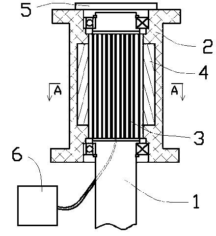
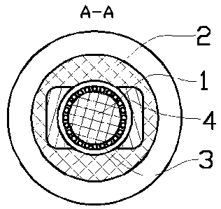
[0015] Such as figure 1 and figure 2 As shown in the embodiment, the electromagnetic reel includes a fixed shaft 1 and a rotating wheel 2; the fixed shaft 1 and the rotating wheel 2 are coaxially rotatable, and the fixed shaft 1 and the rotating wheel Use bearing to connect between wheel 2. The fixed shaft 1 is equipped with a metal coil 3 connected to the circuit, and the inner surface of the rotating wheel 2 is equipped with a pair of magnets 4 ; the position of the magnet 2 is symmetrical with respect to the axis of the fixed shaft 1 .

[0016] The electromagnetic winding wheel is used on the spinning machine, and adopts an electromagnetic structure. By passing an alternating current to the metal coil 3, an alternating magnetic field is generated, and the rotating wheel 2 equipped with a pair of magnets 4 is driven to rotate to complete the winding. action. Since the fixed shaft 1...


PUM


Abstract

The invention provides an electromagnetic reel, and belongs to the technical field of textile machinery. The electromagnetic reel comprises a fixed shaft and a rotary wheel, wherein the fixed shaft and the rotary wheel are assembled in a coaxial and rotary mode. A metal coil which is connected with a switch-in circuit is installed on the fixed shaft. Magnets which exist in a pairing mode are installed on the inner surface of the rotary wheel. The positions of the magnets are symmetrical relative to the center of the axis of the fixed shaft. An electromagnetic structure is adopted, a alternating current is input to the metal coil to produce an alternating magnetic field to drive the rotary wheel which is provided with the pairing magnets to rotate, and therefore the winding action is completed, and the electromagnetic reel only needs to control the input current, direct controlling to parameters like winding force and speed can be achieved.

Description

technical field [0001] The invention belongs to the technical field of textiles, and in particular relates to an electromagnetic winding wheel installed on a spinning machine. Background technique [0002] Yarns are generally made of many short fibers of varying lengths by splicing, as well as long continuous monofilaments. The original yarn is made by hand, which is inefficient; with the advent of the industrial revolution, spinning equipment is gradually replaced by automated equipment. At present, the spinning machine mainly drives two pairs of spinning wheels to rotate in the same direction through electric equipment, imitating the action of twisting, and making cotton, feathers or chemical fibers of various lengths into yarns. [0003] Present spinning machines usually have many pairs of spinning wheels, which can simultaneously spin out multiple yarns. After each yarn is spun, a winding wheel is needed to wind it up for later use. But now the winding wheel usually ad...

Claims


Application Information

Patent Timeline
Patent Type & Authority Applications(China)
IPC IPC(8): D01H1/36
Inventor 赵萍
Owner WUJIANG LANRUITE TEXTILE
Learn More