Power test circuit

A power test and circuit technology, applied in the direction of measuring electrical variables, measuring current/voltage, and measuring electrical power by applying digital technology, it can solve the problem of inability to accurately test the power loss of switching transistors, and achieve the effect of convenient design

Inactive Publication Date: 2014-02-12
HONG FU JIN PRECISION IND (SHENZHEN) CO LTD +1
View PDF0 Cites 1 Cited by
  • Summary
  • Abstract
  • Description
  • Claims
  • Application Information

AI Technical Summary

Problems solved by technology

This test method is easily affected by the test environment and cannot accurately test the actual power loss of the switching transistor

Method used


Image

  • Power test circuit

Examples


Embodiment Construction

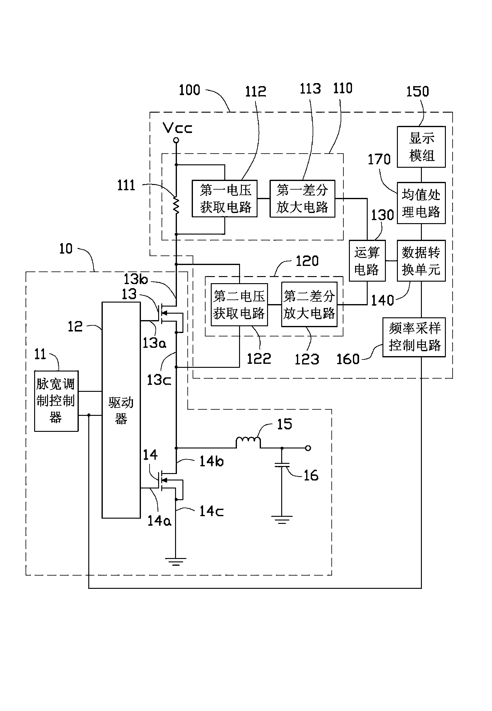
[0010] see figure 1 , figure 1 A schematic circuit diagram of a power test circuit 100 used to detect the power of a switching transistor in the voltage conversion circuit 10 according to a preferred embodiment of the present invention is described.

[0011] The voltage conversion circuit 10 includes a pulse width modulation (Pulse Width Modulation, PWM) controller 11 , a driver 12 , a first switch transistor 13 , a second switch transistor 14 , an inductor 15 , and a capacitor 16 . In this embodiment, the voltage conversion circuit 10 is a typical step-down conversion circuit.

[0012] The pulse width modulation controller 11 is used to output a pulse width modulation signal (PWM signal) to the driver 12, and the driver 12 outputs two pulse signals with opposite phases to the first switching transistor 13 and the second switching transistor 14 according to the PWM signal, The first switching transistor 13 and the second switching transistor 14 are alternately turned on, so ...


PUM


Abstract

The invention provides a power test circuit used for testing the power of a switch transistor in a voltage conversion circuit. The switch transistor comprises a control electrode, a first conduction electrode and a second conduction electrode, and the control electrode is used for controlling the connection and disconnection of the first conduction electrode and the second conduction electrode. The power test circuit comprises a current detection circuit, a voltage detection circuit and an operational circuit, the current detection circuit is used for detecting currents flowing through the first conduction electrode and the second conduction electrode, the voltage detection circuit is used for detecting the voltage difference of the first conduction electrode and the second conduction electrode, the operational circuit receives the currents obtained through the detection of the current detection circuit and the voltage difference obtained through the detection of the voltage detection circuit, and multiplication is carried out on the currents and the voltage difference to obtain the operation result representing the power of the switch transistor.

Description

technical field [0001] The invention relates to a power test circuit, in particular to a power test circuit for testing the power of a switching transistor in a voltage conversion circuit. Background technique [0002] When designing a voltage conversion circuit, such as a step-down conversion circuit (Buck circuit), it is necessary to test the power loss of the switching transistor in the circuit. Currently, a commonly used testing method is to test the heat generation of the switching transistor when it is turned on, turned on and turned off by using an external temperature sensing element to determine the power loss of the switching transistor. This test method is easily affected by the test environment, and cannot accurately test the actual power loss of the switching transistor. Contents of the invention [0003] In view of the above, it is necessary to provide a power test circuit capable of accurately testing the power loss of the switching transistor in the voltag...

Claims


Application Information

Patent Timeline
Patent Type & Authority Applications(China)
IPC IPC(8): G01R21/133G01R19/00
Inventor 周海清
Owner HONG FU JIN PRECISION IND (SHENZHEN) CO LTD
Why Eureka
Try Eureka