Magnetic sensor and manufacturing process thereof

A magnetic sensor and manufacturing process technology, applied in buoy liquid level indicators and other directions, can solve problems such as poor pressure resistance and stability under water immersion, complex structure, etc., and achieve the effects of avoiding contact with water, increasing sensitivity, and prolonging service life.

Active Publication Date: 2013-05-15
FOSHAN CHUANDONG MAGNETOELECTRICITY
View PDF5 Cites 13 Cited by
  • Summary
  • Abstract
  • Description
  • Claims
  • Application Information

AI Technical Summary

Problems solved by technology

[0004] The purpose of the present invention is to provide a magnetic sensitive sensor and its manufacturing process, aiming to solve the tech

Method used


Image

  • Magnetic sensor and manufacturing process thereof
  • Magnetic sensor and manufacturing process thereof
  • Magnetic sensor and manufacturing process thereof

Examples


Embodiment 1

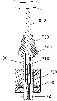
[0036] Such as figure 2 As shown, in this embodiment, the magnetic sensor is set as a reed switch 210 .

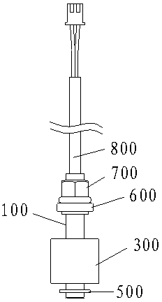
[0037] The magnetic sensor includes a housing 100, a reed switch 210, a float 300, a permanent magnet 400, a limit ring 500, a limit block 600, and a rotating sliding sleeve 700; 210 and the electric wire 800 are welded and placed vertically into the housing 100; in this embodiment, the float 300 is arranged in a ring shape, and the permanent magnet 400 is arranged on the inner surface of the float 300, specifically, the permanent magnet 400 is arranged in a ring shape, The permanent magnet 400 is concentric with the float 300; the shell 100 passes through the float 300, in order to prevent the float 300 from breaking away from the shell 100 in actual work, the upper end of the shell 100 is provided with a limit block 600 to limit the upward movement distance of the float 300, inside the shell 100 The dry reed switch 210 cooperates with the permanent magnet 400 on the in...

Embodiment 2

[0045] In this embodiment, except that the welding position of the reed switch 210 and the electric wire 800 is different from that described in Embodiment 1, other structures are the same as those described in Embodiment 1.

[0046] In this embodiment, the connection mode between the reed switch 210 and the electric wire 800 is as follows Figure 7b as shown, Figure 7b Among them, h4 represents the length of the lead wire at the upper end of the reed switch 210, h5 represents the distance between the bottom end of the glass tube of the reed switch 210 and the welding point between the bottom end of the reed switch 210 and the wire 800, and h6 represents the bottom end of the reed switch 210 and the wire 800 The distance between the welding place and the lowest end of the lead wire at the lower end of the reed switch 210. In the manufacturing process of the magnetic sensor described in the present invention, it is necessary to use resin to fill the housing 100 to protect and...

Embodiment 3

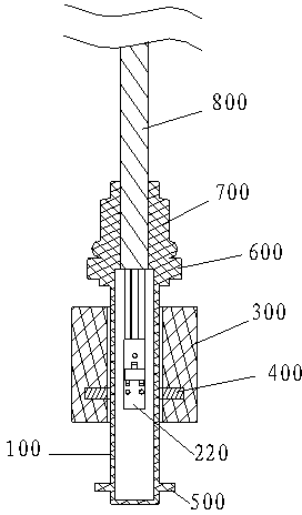
[0048] Such as image 3 As shown, the magnetic sensitive element in this embodiment is MR (Magneto Resistance) magnetoresistor 220, and other structures are the same as those described in Embodiment 1.


PUM

PropertyMeasurementUnit
Thicknessaaaaaaaaaa
Lengthaaaaaaaaaa
Densityaaaaaaaaaa

Abstract

The invention discloses a magnetic sensor and a manufacturing process thereof. The magnetic sensor comprises an outer shell, a magnetic sensitive element and a floater, wherein, the outer shell is in a tubular shape, one end of the outer shell is sealed, the magnetic sensitive element is arranged in the outer shell, an electric wire is connected to the outer side of the magnetic sensitive element, a rotary sliding sleeve used for fixing the electric wire is arranged at the open end of the outer shell, the outer shell is filled with resin, the floater is provided with a permanent magnet, and the floater and the magnetic sensitive element move in a matched mode. The magnetic sensor is high in stability, long in service life, high in reliability and beneficial for production and popularization.

Description

technical field [0001] The invention relates to a sensor and a manufacturing process, in particular to a magnetic sensitive sensor and a manufacturing process. Background technique [0002] Equipment in daily life needs to monitor the water level, such as washing machines, air conditioners, etc. The magnetic sensitive water level monitors in the prior art have short service life, poor water immersion pressure resistance, and are prone to problems such as reduced sensitivity and even failure to work after long-term immersion in water; the existing magnetic sensitive water level monitors have complex structures and are inconvenient to maintain; due to This type of magnetic sensitive water level monitor lacks detection methods such as on-off test, insulation test, and immersion withstand voltage test in the production process, and existing magnetic sensitive water level detectors generally have problems such as poor insulation and poor continuity. [0003] Therefore, the prior...

Claims


Application Information

Patent Timeline
IPC IPC(8): G01F23/72
Inventor 龙克文徐晓兵陈勇胜颜陶
Owner FOSHAN CHUANDONG MAGNETOELECTRICITY
Why Eureka
Try Eureka