Device and method used for testing radio frequency amplifier gain

A radio frequency amplifier and amplifier technology, applied in the direction of electronic circuit testing, etc., can solve the problems of increasing the test cost, high system equipment cost, complex structure, etc., and achieve the effect of low cost, wide test range and high precision

Inactive Publication Date: 2013-05-15
INST OF MICROELECTRONICS CHINESE ACAD OF SCI
View PDF2 Cites 13 Cited by
  • Summary
  • Abstract
  • Description
  • Claims
  • Application Information

AI Technical Summary

Problems solved by technology

[0010] Therefore, the test method for gain in the prior art is relatively traditional, but the structure is relatively complicated, and the cost of system equipment is expensive. Large-scale procurement and testing will greatly increase the test cost

Method used


Image

  • Device and method used for testing radio frequency amplifier gain
  • Device and method used for testing radio frequency amplifier gain
  • Device and method used for testing radio frequency amplifier gain

Examples


Embodiment Construction

[0032] In order to make the object, technical solution and advantages of the present invention clearer, the present invention will be further described in detail below in conjunction with specific embodiments and with reference to the accompanying drawings.

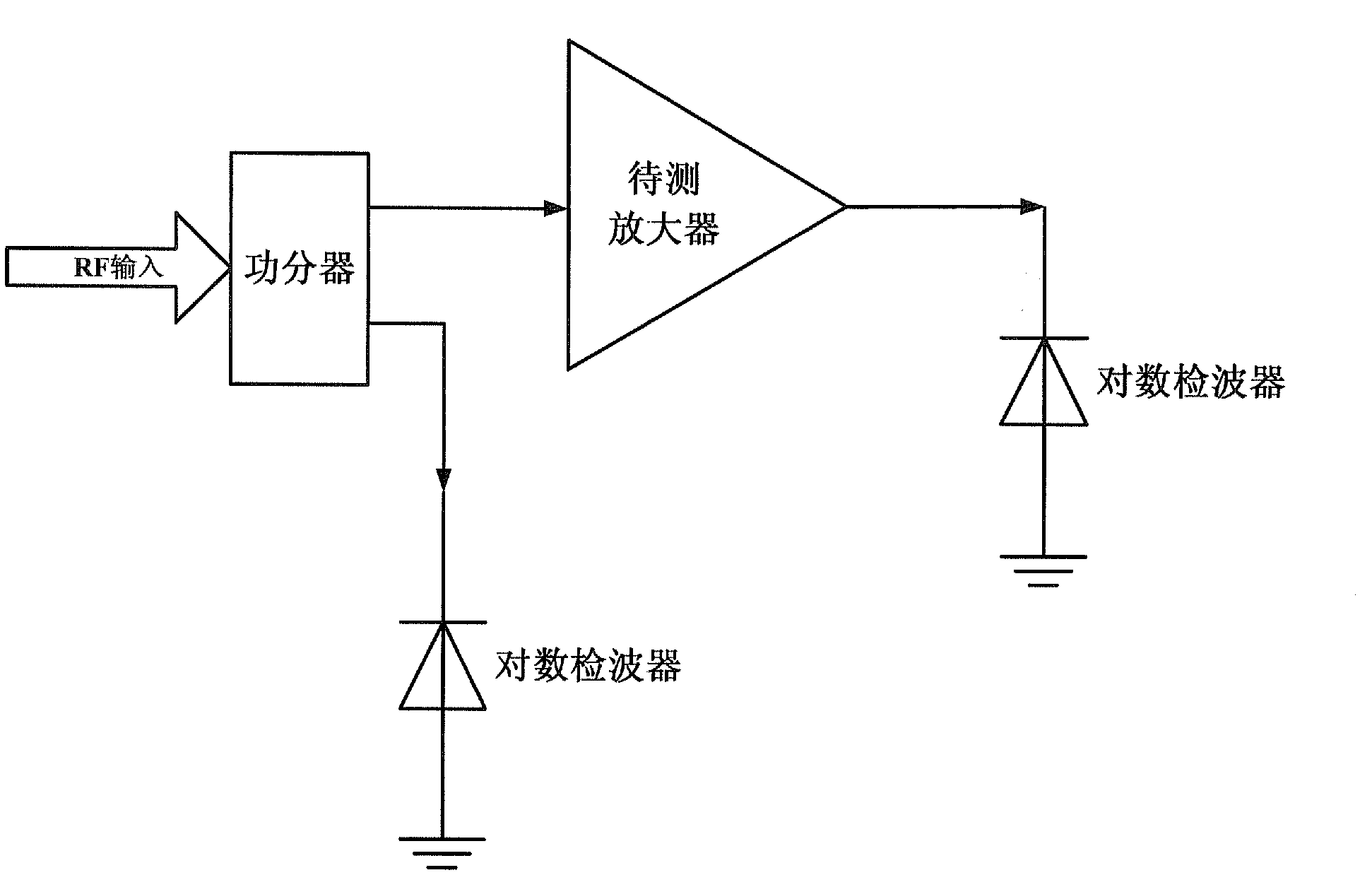
[0033] The present invention replaces the power meter with a high-precision logarithmic detector to test the radio frequency power of the radio frequency amplifier, such as figure 2 as shown, figure 2 It is a structural schematic diagram of a device for testing the gain of a radio frequency amplifier provided by the present invention.

[0034] The device for testing the radio frequency amplifier gain provided by the present invention comprises a power divider, a first logarithmic detector and a second logarithmic detector, wherein the power divider divides the received radio frequency power into two-way signals, and the two-way signals The power difference of the signal can be measured in advance (that is, the power di...


PUM


Abstract

The invention discloses a device and a method used for testing radio frequency amplifier gain. The device for testing the radio frequency amplifier gain comprises a power divider, a first logarithm detector and a second logarithm detector, wherein the power divider is provided with two output ends, one output end is connected with the first logarithm detector, and the other output end is connected with the second logarithm detector through an under-tested amplifier. The device and the method used for testing the radio frequency amplifier gain test power by replacing power meters by the logarithm detectors, so that the cost of the under-tested system is shapely reduced. The device used for testing the radio frequency amplifier gain has the advantage of being simple in structure, low in cost, high in accuracy, wide in testing range, and capable of testing the gain of the amplifier in a range of wide band and power.

Description

technical field [0001] The invention relates to the technical field of gain testing, in particular to a device and method for testing the gain of a radio frequency amplifier. Background technique [0002] Gain testing technology is a very important technology in the field of RF amplifier testing. At present, power dividers and power meters are mainly used to test power and gain, and the high price of power meters makes the cost of the entire test system high. The power meter has too few functions, which reduces the efficiency of the power meter. [0003] Gain testing in the prior art mainly uses signal sources, isolators, frequency meters, variable attenuators, directional couplers, power meters, power supplies, and spectrum analyzers. The specific testing principles are as follows: figure 1 as shown, figure 1 It is a schematic diagram of a gain test system in the prior art. exist figure 1 In the circuit shown, the input power Pi and output power Po of the amplifier unde...

Claims


Application Information

Patent Timeline
Patent Type & Authority Applications(China)
IPC IPC(8): G01R31/28
Inventor 赵志儒阎跃鹏于进勇张晓飞
Owner INST OF MICROELECTRONICS CHINESE ACAD OF SCI
Why Eureka
Try Eureka