Optical fiber coupling connector component and optical fiber coupling connector

A connector component and fiber coupling technology, which is applied in the field of fiber coupling connector components, can solve the problems of low light coupling efficiency, low light coupling efficiency between optical fiber and light receiving module, and achieve the goal of avoiding light loss and ensuring coupling efficiency Effect

Inactive Publication Date: 2013-05-15
HONG FU JIN PRECISION IND (SHENZHEN) CO LTD +1
View PDF4 Cites 3 Cited by
  • Summary
  • Abstract
  • Description
  • Claims
  • Application Information

AI Technical Summary

Problems solved by technology

However, no matter whether the fiber-optic coupling connector is used as the transmitting end of the optical signal or as the receiving end of the optical signal, in the process of optical transmission, the coupling of light between the light emitting module and the optical fiber or the coupling of light between the optical fiber and the receiving module Coupling must be reflected by a coupling lens and changed by 90 degrees. Since the coupling lens will reflect part of the light emitted by the light-emitting module to places other than the optical fiber, the coupling efficiency of light between the light-emitting module and the optical fiber will be poor. High; similarly, since the coupling lens will reflect the light passing through the optical fiber to a place other than the receiving module, the coupling efficiency of the light between the optical fiber and the receiving module will not be high

Method used


Image

  • Optical fiber coupling connector component and optical fiber coupling connector
  • Optical fiber coupling connector component and optical fiber coupling connector
  • Optical fiber coupling connector component and optical fiber coupling connector

Examples


Embodiment Construction

[0016] The embodiments of the present invention will be further described in detail below in conjunction with the accompanying drawings.

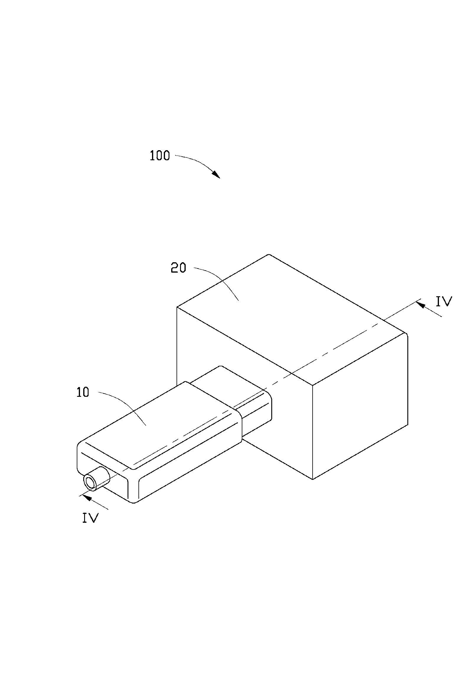
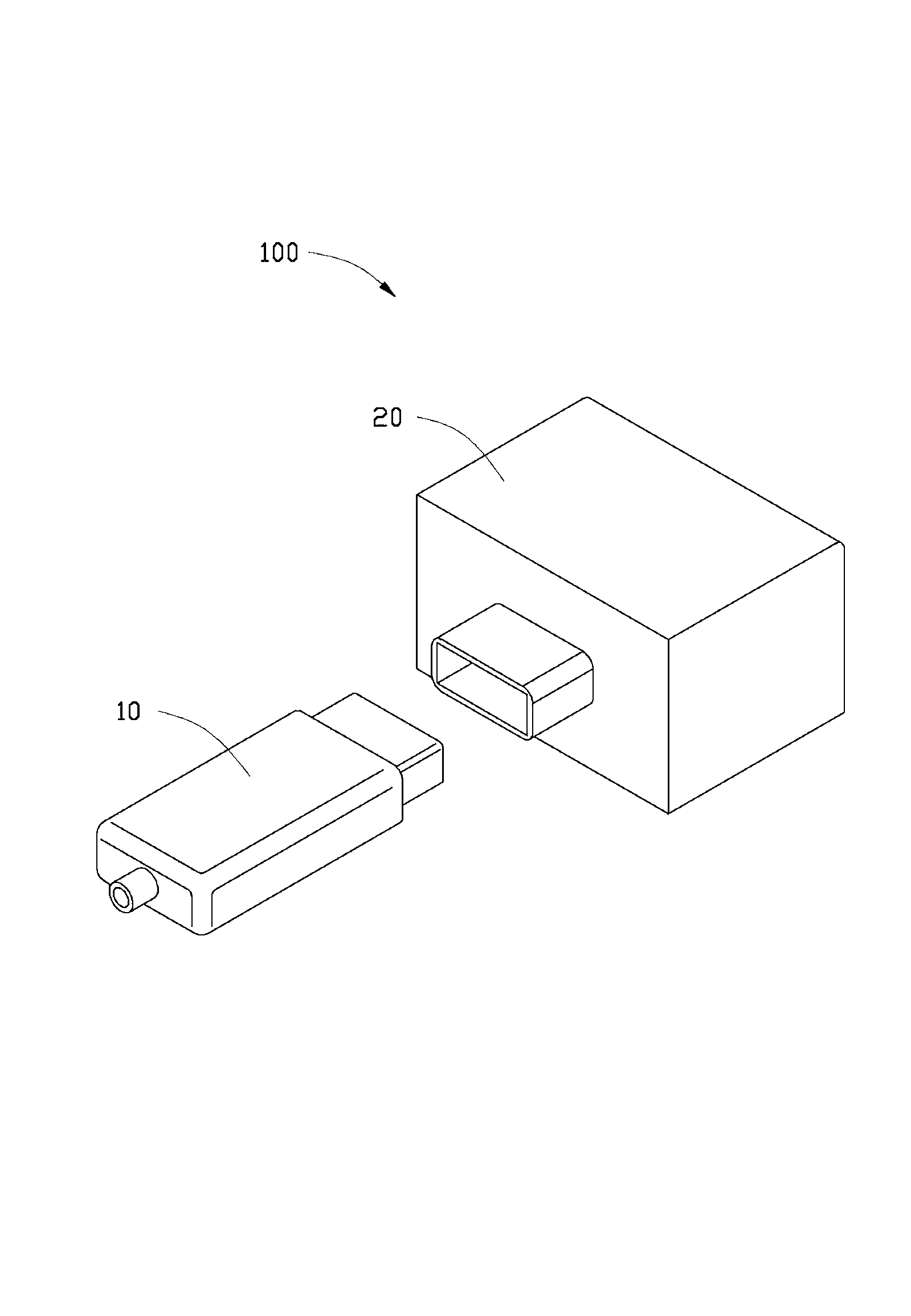
[0017] See figure 1 , Is the optical fiber coupling connector assembly 100 according to the embodiment of the present invention. The optical fiber coupling connector assembly 100 includes a first optical fiber coupling connector 10 and a second optical fiber coupling connector 20 mated with the first optical fiber coupling connector 10. The first optical fiber coupling connector 10 and the second optical fiber coupling connector 20 can perform optical signal transmission after mating.

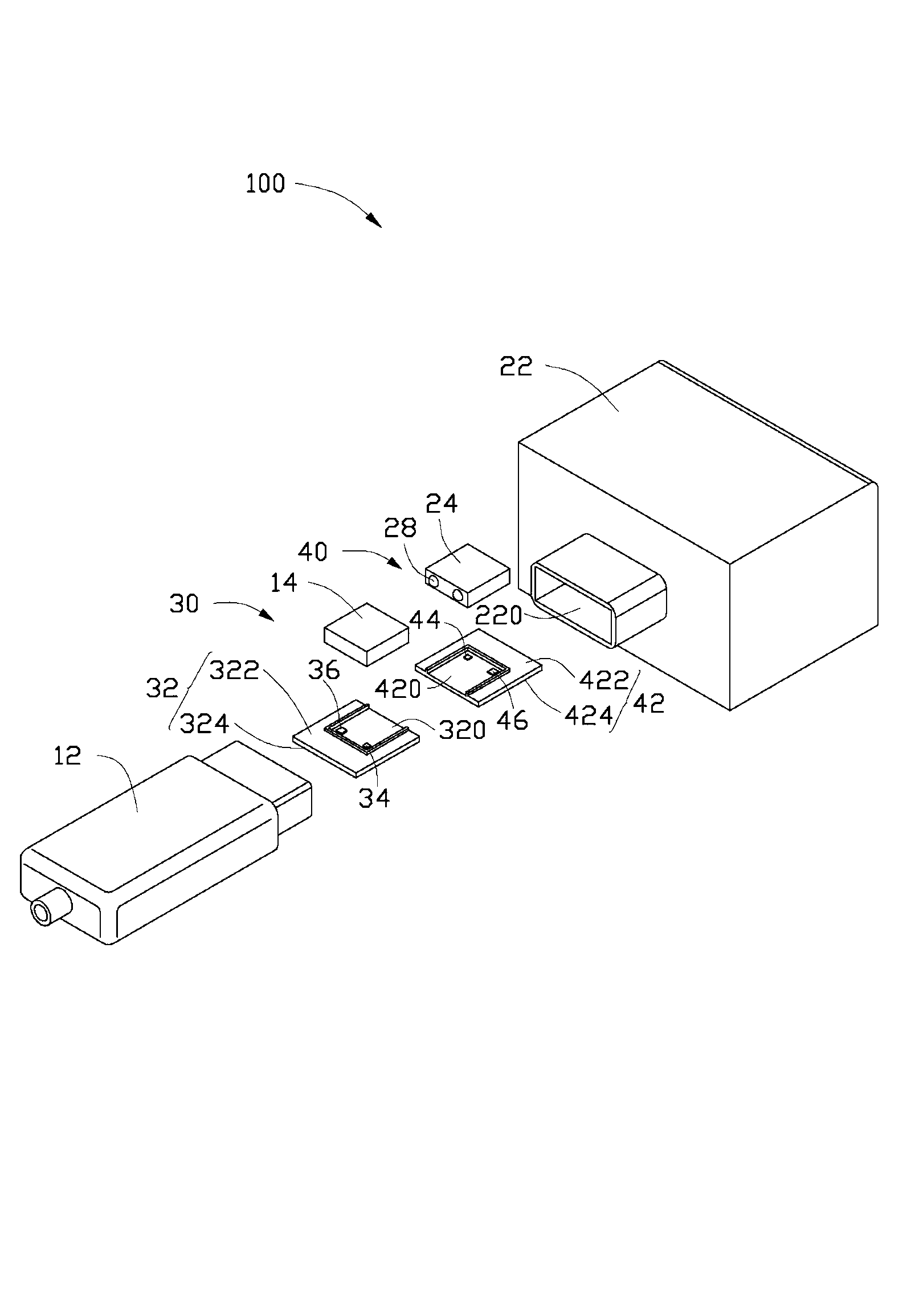
[0018] See Figure 2 to Figure 5 The first optical fiber coupling connector 10 includes a first body 12, a first photoelectric conversion module 30, a first receiving portion 14, two first optical fibers 16 and two first optical lenses 18.

[0019] The first body 12 is provided with a first receiving space 120. In this embodiment, the first receiving space 120 is...


PUM


Abstract

The invention relates to an optical fiber coupling connector which comprises a body, a photoelectric conversion module and two L-shaped optical fibers. The photoelectric conversion module is contained in the body and comprises a substrate, a light emitting module and a light collecting module. The light emitting module and the light collecting module are fixedly arranged on the substrate. The two L-shaped optical fibers are respectively located above the light emitting module and the light collecting module, a port of one of the two L-shaped optical fibers is directed at the light emitting module, and a port of the other one of the two L-shaped optical fibers is directed at the light collecting module. Light ray generated from the light emitting module ejects out after passing through one of the two L-shaped optical fibers, and the light collecting module receives a light ray coupled by the other optical fiber. The invention also relates to an optical fiber coupling connector component.

Description

Technical field [0001] The present invention relates to the field of Universal Serial Bus (Universal Serial Bus, USB), in particular to an optical fiber coupling connector and an optical fiber coupling connector assembly with the optical fiber coupling connector. Background technique [0002] At present, the use of optical signals to transmit data is gradually applied to the USB field of personal computers, and the specific form is embodied in optical fiber coupling connector components. Generally, the optical fiber coupling connector assembly usually includes a first optical fiber coupling connector and a second optical fiber coupling connector that cooperate with each other. Each optical fiber coupling connector includes an optical fiber, an optical lens, a light emitting module, a coupling lens and a light receiving module. Generally, the first optical fiber coupling connector is installed in the first terminal, and the second optical fiber coupling connector is installed in ...

Claims


Application Information

Patent Timeline
Patent Type & Authority Applications(China)
IPC IPC(8): G02B6/32G02B6/38
Inventor 吴开文许义忠
Owner HONG FU JIN PRECISION IND (SHENZHEN) CO LTD
Why Eureka
Try Eureka