Motion positioning control system of vacuum equipment and control method

A technology of positioning control and vacuum equipment, applied in the direction of total factory control, total factory control, electrical program control, etc., can solve the problems of heavy system wiring workload, complex software programming structure, poor scalability, etc., and achieve easy modification and simplified design , easy to maintain and expand the effect

Inactive Publication Date: 2013-05-15
SHENYANG SCI INSTR RES CENT CHINESE ACAD OF SCI
View PDF5 Cites 1 Cited by
  • Summary
  • Abstract
  • Description
  • Claims
  • Application Information

AI Technical Summary

Problems solved by technology

The software programming structure of this method is complicated. If the motor drive controller is at the remote end, the system wiring workloa

Method used


Image

  • Motion positioning control system of vacuum equipment and control method
  • Motion positioning control system of vacuum equipment and control method
  • Motion positioning control system of vacuum equipment and control method

Examples


Example Embodiment

[0041] The solution of the present invention will be further described in detail below in conjunction with the drawings and embodiments.

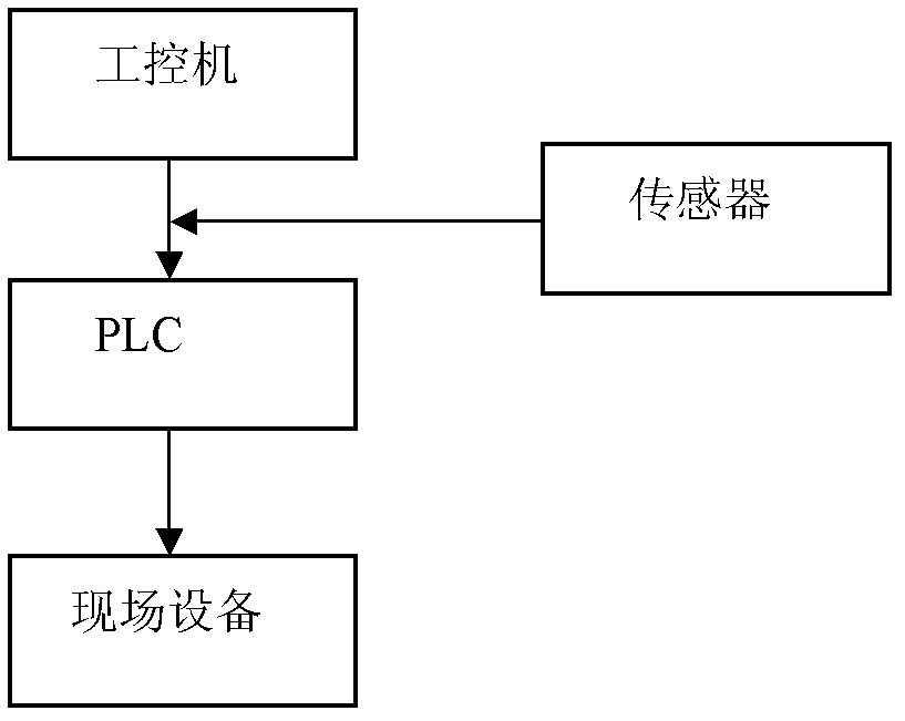
[0042] Such as figure 1 Shown is a block diagram of the system of the present invention. It is the system block diagram of the present invention. The invention is a vacuum equipment movement positioning control system, which is characterized by including PLC, industrial computer, field equipment and sensors; among them, PLC is the main control component, and its input terminal receives the field sensor signal, communicates with the industrial computer, and outputs Terminate field equipment; the industrial computer is the upper computer of the PLC, and the PLC control program is programmed, and the field equipment is controlled through the PLC. The field equipment includes a stepper motor driver and / or an AC servo motor driver and a motor. The motor is connected to the field sensor input terminal.

[0043] In this embodiment, the PLC uses the C...


PUM


Abstract

The invention discloses a motion positioning control system of vacuum equipment and a control method. The motion positioning control system of the vacuum equipment comprises a programmable logic controller (PLC), an industrial personal computer (IPC), on-site equipment and an on-site sensor, wherein the PLC is a master control component, an input end of the PLC receives signals of the on-site sensor and is in communication connection with the IPC, and an output end of the PLC is connected with the on-site equipment. The on-site equipment comprises a stepping motor driver and/or alternative current servo motor driver and a motor, and is connected with an input end of the on-site sensor through the motor. The IPC is an upper computer of the PLC, programs a control program of the PLC and controls the on-site equipment through the PLC. The control method of the motion positioning control system includes that by means of a parameter collocation method and an order judgment design, the system processes each motion in an order mode. The control method is simple in program design, easy to modify, and capable of achieving vacuum motion system circumferential positioning according to on-site conditions and process requirements.

Description

technical field [0001] The invention belongs to the technical field of vacuum equipment positioning, and in particular relates to a vacuum equipment motion positioning control system and a control method. technical background [0002] Vacuum coating equipment needs to control the position of the sample in the vacuum chamber during the coating process of the sample. In order to realize the positioning control hardware, a PC + motion control card is usually used, or a PLC-specific positioning module is used to realize it. The software needs to be programmed separately for processing. . The software programming structure of this method is complicated. If the motor drive controller is at the remote end, the system wiring workload will be heavy; the scalability is poor. If the number of motion controllers needs to be increased, the control system needs to be reprogrammed. Contents of the invention [0003] Aiming at the above-mentioned technical problems, the present invention...

Claims


Application Information

Patent Timeline
IPC IPC(8): G05B19/418
CPCY02P90/02
Inventor 戚晖耿达林秀青徐英凤
Owner SHENYANG SCI INSTR RES CENT CHINESE ACAD OF SCI
Why Eureka
Try Eureka