Microvoid wire threading locating mechanism
What is Al technical title?
Al technical title is built by PatSnap Al team. It summarizes the technical point description of the patent document.
A positioning mechanism and wire threading technology, applied in fuse manufacturing and other directions, can solve the problems that the threading quality and product quality cannot be guaranteed, the fuse wire is easily deformed, and the accuracy and success rate are limited, so as to improve the efficiency of threading and threading. The effect of quality, compact structure and high positioning accuracy
Inactive Publication Date: 2015-05-20
SHANGHAI UNIV OF ENG SCI
View PDF4 Cites 0 Cited by
Summary
Abstract
Description
Claims
Application Information
AI Technical Summary
This helps you quickly interpret patents by identifying the three key elements:
Problems solved by technology
Method used
Benefits of technology
Problems solved by technology
The traditional wire threading machine uses a hyperboloid face-to-wheel mechanism to thread the wire directly, the fuse wire is prone to deformation, and the accuracy and success rate are greatly limited; while the manual threading efficiency is low, and the quality of threading and product quality cannot be guaranteed.
Method used
Image
Click on the blue label to locate the original text in one second.
Reading with bidirectional positioning of images and text.
Examples
Embodiment
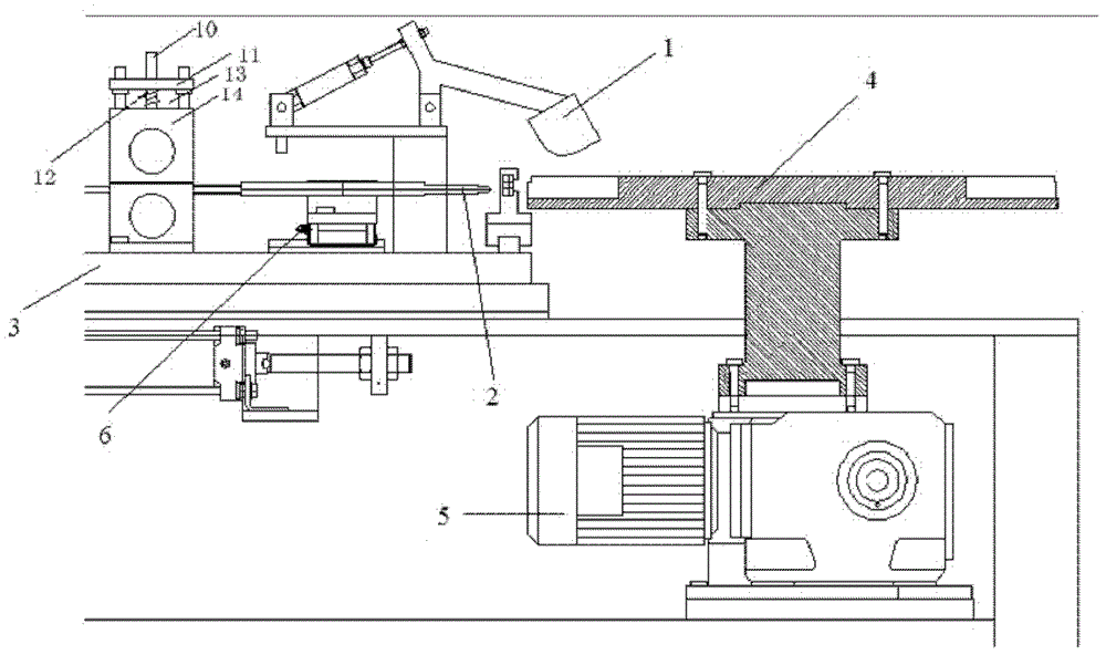
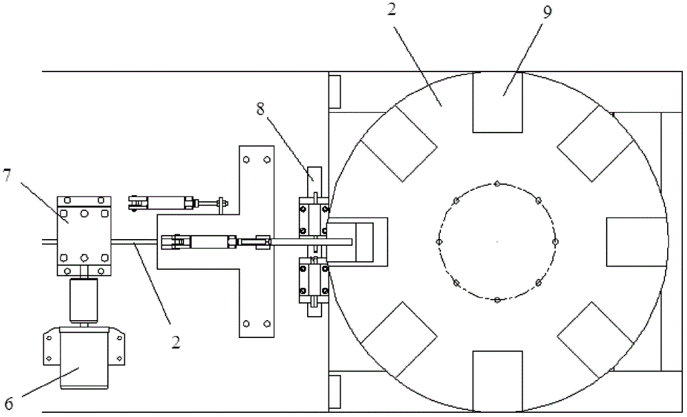
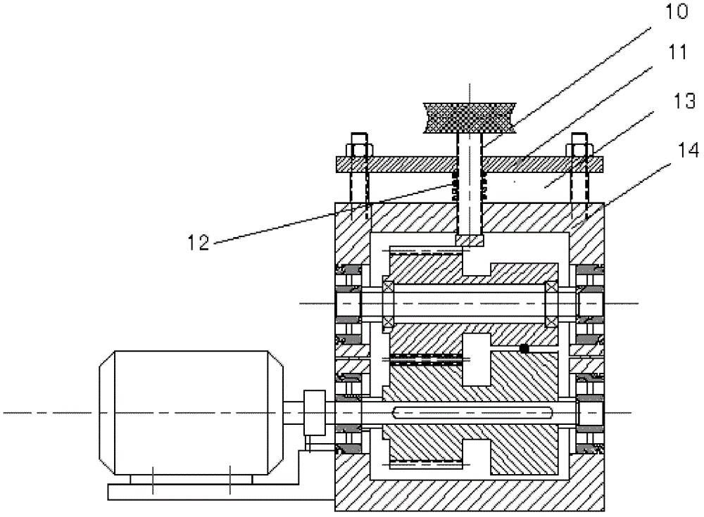
[0027] Such as Figure 1-2 As shown, a microhole threading positioning mechanism includes a turntable 4, a first motor 5, a capillary threading tube 2, a counter wheel wire feeding device, an upper cover plate 1, a negative electrode 8, a workbench 3, and a second motor 6 , the pair of wire feeding devices includes a pair of wire feeding rollers 7, a corresponding drive motor with the wire feeding rollers 7 and a controller for controlling the rotation angle of the driving motor, a pair of wire feeding rollers 7 as the main wheel and the slave The surface of the main wheel and the slave wheel are concave and convex, and the nominal diameters of the master wheel and the slave wheel are completely equal.
[0028] The lower end of the turntable 4 is provided with a stepping rotation mechanism, the upper end of the stepping rotation mechanism cooperates with the turntable 4, and the lower end is connected with the output shaft of the first motor 5, which is a stepping motor and dr...
PUM
Abstract
The invention relates to a microvoid wire threading locating mechanism which comprises a rotating plate, a first motor, a thin diameter wire threading tube, an opposite-wheel wire feed device, an upper cover plate, a negative electrode, an operating platform and a second motor, wherein a stepping rotating mechanism is arranged at the lower end of the rotating plate, locating grooves used for containing work pieces are formed in the rotating plate, an output shaft of the first motor is connected with the stepping rotating mechanism at the lower end of the rotating plate, the thin diameter wire threading tube is fixed on the operating platform, one end of the thin diameter wire threading tube directly faces a wire threading station on the rotating plate, the opposite-wheel wire feed device is arranged at the end head of the other end of the thin diameter wire threading tube, the opposite-wheel wire feed device is fixedly arranged on the operating platform, the upper cover plate is arranged above the wire threading station, the negative electrode is arranged on one side, between the wire threading station and the thin diameter wire threading station, of the operating platform, the negative electrode is connected with an air cylinder, and the operating platform is connected with the second motor. Compared with the prior art, the microvoid wire threading locating mechanism has the advantages of being capable of rapidly and accurately threading wires for a fuse protector, high in automation degree, good in robustness, capable of improving working efficiency and the like.
Description
technical field [0001] The invention relates to a microhole wire threading positioning mechanism, in particular to automatic wire threading equipment in the production process of low-voltage fuses. Background technique [0002] With the technological advancement of electrical products, automatic wire threading plays a pivotal role in today's automated production lines, especially in the process of producing fuses, which is an important link in fuse assembly. However, most of the traditional wire threading equipment have shortcomings such as slow speed, poor precision, and narrow application range. Taking the design background of this mechanism as an example, the traditional wire threading process of low-voltage fuses is done manually, which has high randomness, low yield and low output. In the actual production of the fuse, it is required that the fuse wire of 0.25mm passes through the microhole of 0.35mm, and the allowable error on one side is only 0.05mm; at the same time...
Claims
Application Information
Patent Timeline
Application Date:The date an application was filed.
Publication Date:The date a patent or application was officially published.
First Publication Date:The earliest publication date of a patent with the same application number.
Issue Date:Publication date of the patent grant document.
PCT Entry Date:The Entry date of PCT National Phase.
Estimated Expiry Date:The statutory expiry date of a patent right according to the Patent Law, and it is the longest term of protection that the patent right can achieve without the termination of the patent right due to other reasons(Term extension factor has been taken into account ).
Invalid Date:Actual expiry date is based on effective date or publication date of legal transaction data of invalid patent.