D-type radio-frequency power amplifying circuits
A radio frequency power and amplifying circuit technology, applied in the field of electronics, can solve problems such as power amplifier hazards, and achieve the effect of improving stability and power output efficiency
- Summary
- Abstract
- Description
- Claims
- Application Information
AI Technical Summary
Problems solved by technology
Method used
Image


Examples
Embodiment 1
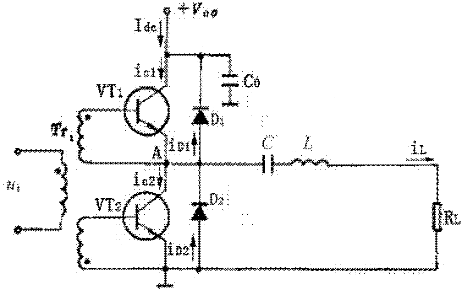
[0021] see figure 2 A class D radio frequency power amplifier circuit provided by an embodiment of the present invention includes a class D power amplifier and a transistor protection circuit. Wherein, the class D power amplifier includes a first transistor VT1, a second transistor VT2, a voltage transformer, a capacitor C0, a capacitor C, an inductor L and a resistor RL. The transistor protection circuit includes a diode D1 and a diode D2. The diode D1 is connected between the collector of the first transistor VT1 and the emitter of the first transistor VT1; the diode D2 is connected between the collector of the second transistor VT2 and the emitter of the second transistor VT2. A transistor protection circuit is added to the circuit so that the negative current in each high-frequency cycle flows through D1 and D2 respectively, and the capacitor C will not generate a large pulse peak voltage, thereby protecting the transistor well. In addition, in the actual circuit, the d...
Embodiment 2
[0023] The characteristic of the class D power amplifier is to work in the switch state, and the switching process of the two power amplifiers is controlled by the waveform and amplitude of the excitation signal. Therefore, the efficiency of the power amplifier is closely related to the waveform and amplitude of the excitation signal. The efficiency of rectangular wave excitation is higher than that of sine wave excitation, because when rectangular wave is used as excitation, the switching transition of the two switching tubes is faster, the transient process is shorter, and the efficiency of the amplifier is bound to be higher.
[0024] see image 3 The class D radio frequency power amplifying circuit provided by the embodiment of the present invention can not only meet the requirements of the class D power amplifier on the waveform and amplitude of the excitation signal when the power amplifier works at high efficiency, but also protect the transistor. The class D radio fre...
Embodiment 3
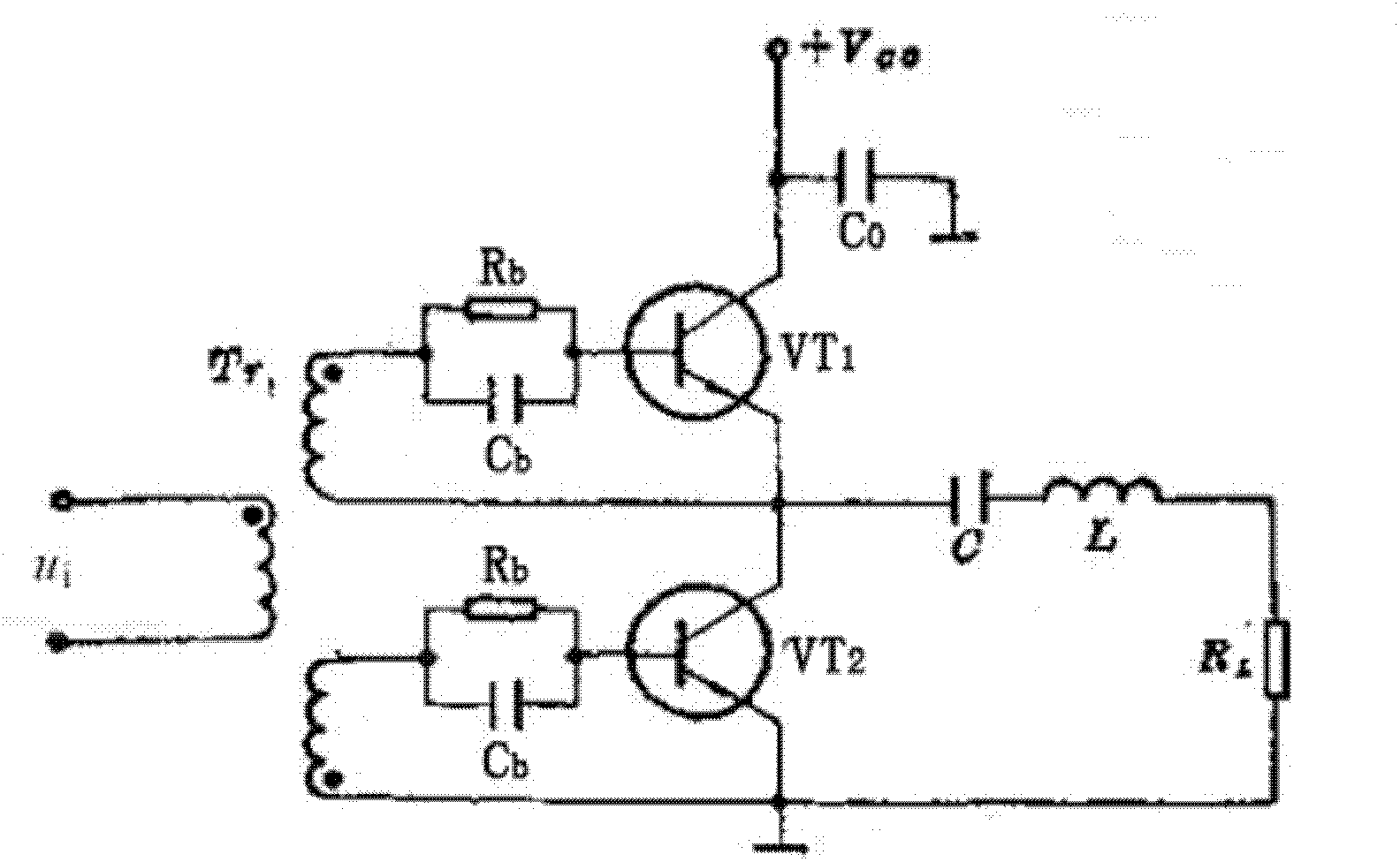
[0028] In order to further improve the stability and power output efficiency of the Class D power amplifier, see Figure 4, the embodiment of the present invention proposes a class D radio frequency power amplifier circuit, which includes a class D power amplifier, a transistor protection circuit and two RC circuits. Among them, the class D power amplifier includes a first transistor VT 1 , the second transistor VT 2 , voltage transformer, capacitor C 0 , capacitor C, inductor L and resistor RL. The transistor protection circuit consists of a diode D 1 , Diode D 2 . Diode D 1 connected to the first transistor VT 1 collector and the first transistor VT 1 between the emitter stages; diode D 2 connected to the second transistor VT 2 collector and the second transistor VT 2 between the launch stages. An RC circuit is connected between the voltage transformer and the first transistor VT 1 Between the base stage, another RC circuit is connected between the voltage trans...
PUM
 Abstract
Description
Claims
Application Information
 - R&D
- Intellectual Property
- Life Sciences
- Materials
- Tech Scout
- Unparalleled Data Quality
- Higher Quality Content
- 60% Fewer Hallucinations
Browse by: Latest US Patents, China's latest patents, Technical Efficacy Thesaurus, Application Domain, Technology Topic, Popular Technical Reports.
© 2025 PatSnap. All rights reserved.Legal|Privacy policy|Modern Slavery Act Transparency Statement|Sitemap|About US| Contact US: help@patsnap.com