
Method for finishing upper groove and narrow slit of workpiece

A technology for narrow slits and workpieces, which is applied in the field of finishing grooves and narrow slits on workpieces. It can solve problems such as inaccessibility of finishing equipment and tools, defects in the appearance of manufactured products, and low transmission accuracy, so as to improve mechanical and physical properties and facilitate operation. , a wide range of effects

Inactive Publication Date: 2013-05-22
UNIV OF SCI & TECH LIAONING
View PDF5 Cites 20 Cited by
  • Summary
  • Abstract
  • Description
  • Claims
  • Application Information

AI Technical Summary

Problems solved by technology

Most of these grooves and slits are small in size (groove width 0.1mm-10mm, groove depth 0.1mm-8mm), and it is difficult to smooth the two sides and bottom surfaces of them by traditional grinding and polishing technology, especially on the inner surface of the workpiece. slots and slits in the slits are out of reach for many finishing equipment and tools due to limited space
If the finishing precision of the grooves and slits on the mold is not enough, it may cause appearance defects of the manufactured product; if the surface finishing precision of the inner ring surface of the bearing, the surface of the precision spline keyway, and the thread surface of small bolts and nuts is low, it will cause transmission defects. Problems such as low precision, loud working noise, and loose fastening

Method used


Image

  • Method for finishing upper groove and narrow slit of workpiece
  • Method for finishing upper groove and narrow slit of workpiece
  • Method for finishing upper groove and narrow slit of workpiece

Examples


Embodiment 1

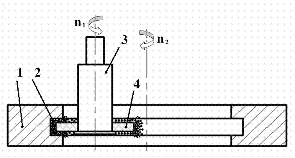
[0024] Such as figure 1 As shown, the method for finishing the rectangular groove of P20 die steel workpiece.

[0025] (1) Using equipment and materials

[0026] A refitted vertical milling machine is adopted, the spindle speed ranges from 300 to 3000r / min, the workpiece positioning frame adopts K11 series standard three-jaw self-centering chuck, and its flip angle is adjustable, driven by a three-phase AC motor with a speed of 50 ~300r / min, can adjust forward and reverse.

[0027] The annular permanent magnet 4 is made of NdFeB, magnetized radially, and the size is The magnetic chuck 3 is connected to the main shaft of the vertical milling machine, and is driven to rotate by the main shaft. The magnetic abrasive grains 2 used are composite grains of iron grains and aluminum oxide grains prepared through briquetting, sintering, crushing and screening processes.

[0028] (2) Operation steps

[0029] Workpiece 1 has a rectangular ring groove, the size of which is The wor...

Embodiment 2

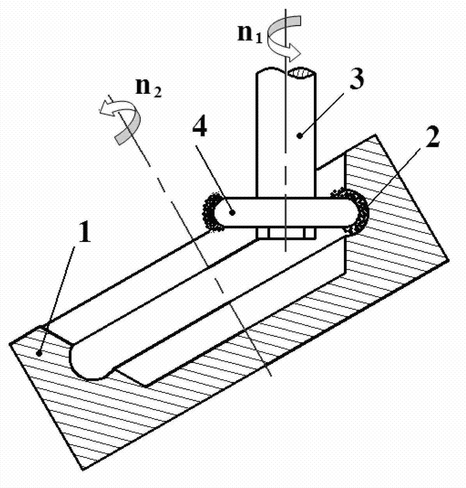
[0031] Such as figure 2 As shown, the method for finishing the curved chute of P20 die steel workpiece.

[0032] (1) The equipment and materials used are the same as in Example 1.

[0033] (2) Operation steps:

[0034] The workpiece 1 has an arc-shaped ring groove, the radius of curvature of the arc is r=1.2mm, and the diameter of the arc top is The workpiece 1 is fixed by the chuck of the positioning frame, and is driven by the motor to rotate at a speed n 2 =300r / min. The permanent magnet 4 is made of NdFeB, ring-shaped, and the diameter of the inner surface is The outer surface is a semi-arc surface, the radius of curvature r=1.2mm, and the diameter of the arc top is The thickness is 1.5mm. The permanent magnet 4 is connected to the main shaft of the milling machine by the magnetic chuck 3, and is driven to rotate by the main shaft at a speed n 1 =1300r / min. Adjust the angle of the positioning frame so that the gap between the arc-shaped surface of the permanent...

Embodiment 3

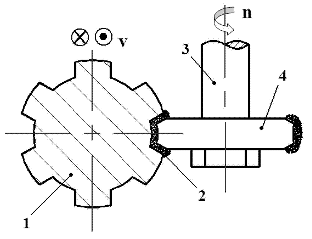
[0036] as attached image 3 As shown, the method of finishing the rectangular spline groove on the workpiece.

[0037] (1) The equipment and materials used are the same as in Example 1.

[0038] (2) Operation steps:

[0039] Workpiece 1 is a rectangular spline shaft made of 45 steel with a size of 6-20×25×6mm. Workpiece 1 is fixed by the chuck of the positioning frame and driven by the positioning frame to reciprocate along the axial direction. The moving speed is v= 1mm / s. The permanent magnet 4 is made of NdFeB, ring-shaped, and the diameter of the inner surface is The outer surface is a semi-arc surface, the radius of curvature r=10mm, and its thickness is 4mm. The permanent magnet 4 is connected to the main shaft of the milling machine by the magnetic chuck 3, and is driven to rotate by the main shaft at a speed n=1300r / min. Adjust the angle of the positioning frame so that it maintains a 1mm gap with the bottom of the spline groove of the workpiece 1 and both sides ...


PUM

PropertyMeasurementUnit
surface roughnessaaaaaaaaaa

Abstract

The invention discloses a method for finishing an upper groove and a narrow slit of a workpiece. The method for finishing the upper groove and the narrow slit of the workpiece can enable the surface quality of the upper groove and the narrow slit of the workpiece to be improved obviously. A set of mechanical equipment with a power rotation main shaft is adopted, so that an annular permanent magnet is fixedly arranged on the rotation main shaft through a clamp, and the workpiece is fixed by using a workpiece positioning frame. Magnetism abrasive particles are covered on the surface of a to-be-finished groove or a to-be-finished narrow slit of the workpiece, the annular permanent magnet is enabled to aim at the to-be-finished position for magnetic abrasive finishing, due to magnetic force, the magnetism abrasive particles are attached to the surface of the to-be-finished groove or the to-be-finished narrow slit of the workpiece in a pressing mode, the annular permanent magnet is driven to rotate by a main shaft motor, the magnetism abrasive particles conduct abrasion and squeezing to the groove or the narrow slit in the workpiece, and so that polishing and burring are achieved. The method for finishing the upper groove and the narrow slit of the workpiece is wide in range of application, concise in method, easy to operate, and capable of not only being used for die workpieces, but also being used for finishing of a circular groove in the inner surface of a hydraulic cylinder, the surface of a bearing inner race, the surface of a precise spline key groove and the threaded surfaces of a small bolt and a nut.

Description

technical field [0001] The invention relates to a grinding and polishing method, in particular to a method for smoothing grooves and slits on workpieces. Background technique [0002] With the rapid development of the mold industry, the surface of the mold is becoming more and more complex, and the processing accuracy requirements are also becoming higher. How to smooth the grooves and narrow slits on the mold to meet various design requirements has become more and more important. The more it arouses the attention of manufacturers. The same problem also widely exists in the circular groove of the inner surface of the hydraulic cylinder, the surface of the inner ring of the bearing, the surface of the precision spline keyway, the smooth surface of the thread of the small bolts and nuts, etc. Most of these grooves and slits are small in size (groove width 0.1mm-10mm, groove depth 0.1mm-8mm), and it is difficult to smooth the two sides and bottom surfaces of them by traditiona...

Claims


Application Information

Patent Timeline
Patent Type & Authority Applications(China)
IPC IPC(8): B24B1/04
Inventor 陈燕焦安源曲涛王显康郭龙文李宗泽
Owner UNIV OF SCI & TECH LIAONING
Learn More