Supercharge Your Innovation With Domain-Expert AI Agents!

Movable stand shifting device

A technology of mobile device and movable stand, which is applied in the direction of lifting device, lifting frame, etc., can solve the problems of high manufacturing cost and complex structure of the movable stand, and achieve the effects of low manufacturing cost, simple structure and convenient use.

Inactive Publication Date: 2013-05-22
浙江神鸽实业有限公司
View PDF7 Cites 0 Cited by
  • Summary
  • Abstract
  • Description
  • Claims
  • Application Information

AI Technical Summary

Problems solved by technology

"The problem that exists is: described lateral moving car is actually a component part of movable stand, and movable stand needs to be specially made, and a movable stand needs to be fixedly equipped with a group of lateral moving cars, and each moving car then needs to be equipped with four wheels, so The structure of the horizontally moving vehicle and the corresponding movable stands is complicated, and the processing and manufacturing costs are high

Method used


Image

  • Movable stand shifting device
  • Movable stand shifting device
  • Movable stand shifting device

Examples


Embodiment 1

[0018] The technical solutions of the present invention will be further specifically described below through the embodiments and in conjunction with the accompanying drawings.

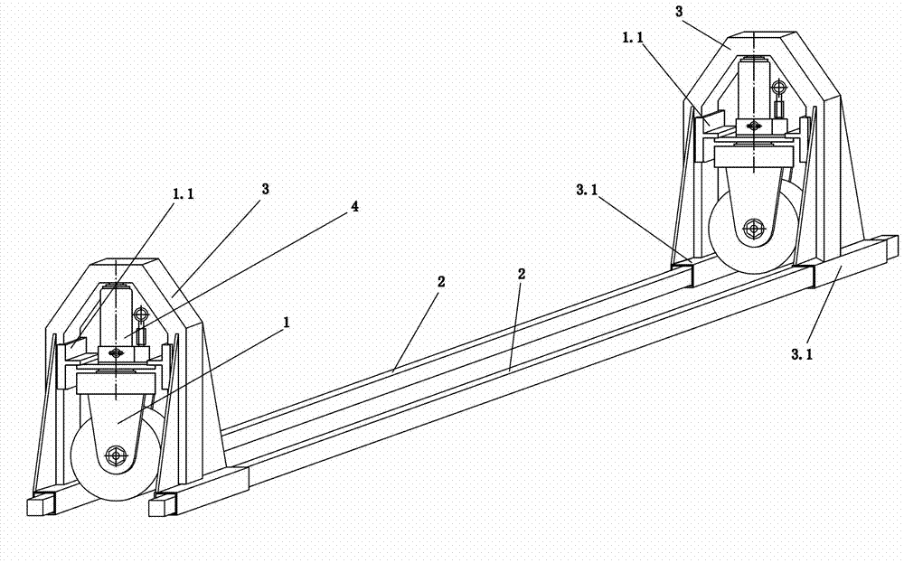
[0019] like figure 1 As shown, the present invention comprises caster 1, support bar 2, support bar frame 3 and jack 4; Each caster 1 is equipped with a support bar frame 3 and a jack 4 to form a walking foot; The outline is square, the bracket 3 is an inverted U-shaped part, the piston of the jack 4 is fixedly connected with the middle part of the upper end of the bracket 3, the base of the jack 4 is fixedly connected with the wheel frame of the caster 1; The lower ends of the sides are respectively provided with a supporting rod connection hole that is movable with the supporting rod; every two walking feet and two supporting rods 2 parallel to each other are combined to form a walking frame, and the two ends of each supporting rod are connected with two supporting rods respectively. The lower end o...

Embodiment 2

[0021] The difference between the second embodiment and the first embodiment is that the guide 1.1 of the second embodiment is a vertical rod, the lower end of which is fixedly connected with the wheel frame of the caster (1), and the upper end is connected with the guide provided at the upper end of the bracket (3). Hole slip fit.

Embodiment 3

[0022] The difference between the third embodiment and the first embodiment is that the guide piece 1.1 of the third embodiment is a slider piece adapted to the vertical guide groove provided on the inner surface of the side of the bracket (3), and the number of pieces is two. Correspondingly, the inner surfaces of the two sides of the bracket (3) are provided with a vertical guide groove.

[0023] In the above embodiments, the square tube-shaped support rod can be replaced by a circular tube-shaped support rod, and the corresponding support rod connecting hole is replaced by the inner hole of the circular tube 3.1 welded to the lower ends of the two sides of the support rod frame 3. Form, now when the walking feet are socketed with the two round pipes, a connecting rod should be used to connect the two round pipes to prevent the round rods from rolling. In addition, the two support rods in the above embodiments can also be replaced by a support rod with a U-shaped plug joint ...


PUM


Abstract

A movable stand shifting device comprises trundles, supporting rods, supporting rod frames and a lifting jack, each trundle is matched with one supporting frame, the trundles and the lifting jack form walking legs, the supporting rod frames are conversed U-shaped workpieces, a piston of the lifting jack is fixedly connected with the middle portion of the upper portion of each supporting rod frame, a base of the lifting jack is fixedly connected with wheel frames of the trundles, the lower ends of two side edges of each supporting rod frame are provided with a supporting rod connecting hole which is movably matched with the supporting rods, a walking frame is formed by every two walking legs and two parallel supporting rods or a supporting rod which is respectively provided with a U-shaped connector at two ends, wherein the two ends of one supporting rod are respectively movably connected with the lower ends of the supporting rod frames of two walking legs through the supporting rod connecting holes, and the supporting frames of the trundles are at least fixedly provided with a guiding part which is matched with the supporting rod frames. The movable stand shifting device has the advantages of being simple in structure, reliable and stable in work, low in processing and manufacturing costs, suitable for transporting and shifting various movable stands, capable of providing for the various movable stands to share, convenient to use, low in use cost, safe and reliable.

Description

technical field [0001] The invention relates to a conveying and transferring device, in particular to a conveying and transferring device for a movable stand. [0002] Background technique [0003] The event stands used in places such as large studios and stadiums often need to be folded up for transfer or storage. This position transfer not only needs to move the movable stands back and forth, but also often requires lateral movement and rotation. In the prior art, forklifts are usually used to transfer and carry movable stands. For large and medium-sized stands longer than 6 meters, with one forklift, the two ends of the stand are prone to bending deformation and damage. If multiple forklifts are used, the Difficult to coordinate. It is also easy to have an overturning accident when using a forklift to transfer and carry the activity stand. [0004] Announced on November 21, 2007, the announcement number is CN200978537Y, and the Chinese patent document titled "A kind o...

Claims


Application Information

Patent Timeline
Patent Type & Authority Applications(China)
IPC IPC(8): B66F7/00
Inventor 王文明
Owner 浙江神鸽实业有限公司
Features
  • R&D
  • Intellectual Property
  • Life Sciences
  • Materials
  • Tech Scout
  • Unparalleled Data Quality
  • Higher Quality Content
  • 60% Fewer Hallucinations
Learn More