Cross-flow internally-cooled solution dehumidifier and method thereof

A solution dehumidification and cooling technology, applied in chemical instruments and methods, separation methods, heating methods, etc., can solve the problems of decreased dehumidification efficiency and increased temperature of dehumidification solution, and achieve the effect of reducing air side pressure and improving dehumidification performance.

Inactive Publication Date: 2013-05-22
ZHEJIANG UNIV
View PDF5 Cites 11 Cited by
  • Summary
  • Abstract
  • Description
  • Claims
  • Application Information

AI Technical Summary

Problems solved by technology

In the adiabatic dehumidifier, when the water vapor in the humid air is absorbed by the dehumidification solution, it will release the latent heat of phase change, which will increase the temperature of the dehumidification solution and reduce the dehumidification efficiency.

Method used


Image

  • Cross-flow internally-cooled solution dehumidifier and method thereof
  • Cross-flow internally-cooled solution dehumidifier and method thereof
  • Cross-flow internally-cooled solution dehumidifier and method thereof

Examples


Embodiment

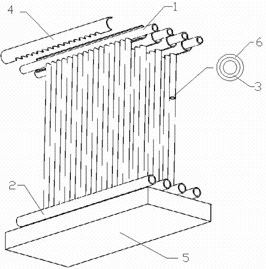
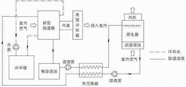
[0023] Air conditioning systems using cross-flow internally cooled solution dehumidifiers. The system is mainly composed of dehumidifier, regenerator, surface cooler, fan, cooling tower, dilute solution pool, concentrated solution pool, solution heat exchanger, heater, water pump, and solution pump.

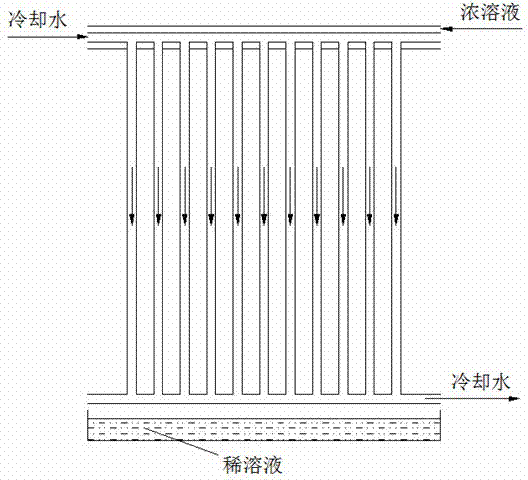
[0024] After the dehumidification solution flows into the casing, it will flow down the capillary and be evenly distributed outside the capillary by the capillary suction of the corduroy. When the humid air passes horizontally between the parallel plates, it contacts with the dehumidification solution and undergoes heat and mass transfer to complete the dehumidification process. The dilute solution that has absorbed water vapor and latent heat of vaporization is collected by the sump and flows out of the dehumidifier to the dilute solution pool, and then the solution is pumped to the heat exchanger to release heat. The dilute solution flowing out of the heat exchanger flows into...


PUM


Abstract

The invention discloses a cross-flow internally-cooled solution dehumidifier and a method thereof. The cross-flow internally-cooled solution dehumidifier is composed of a plurality of dehumidifying units which are arranged side by side or connected in series. The dehumidifying units comprise distributive pipes, collecting pipes, capillary pipes, sleeves, liquid collecting grooves and liquid absorbing layers. The distributive pipes are provided with a plurality of capillary pipes in vertical and parallel modes, the collecting pipes are arranged at the ends of the plurality of capillary pipes, the liquid collecting grooves are arranged below the collecting pipes, the sleeves are arranged outside the distributive pipes, and one or more liquid absorbing layers are evenly and tightly wound outside each capillary pipe. Compared with the prior art, the cross-flow internally cooled solution dehumidifier and the method thereof have the advantages that first, the mass flow rate of solutions consumed by the dehumidifier is smaller than that of solutions consumed by a traditional tower type dehumidifier when moisture air with the same mass flow rate is processed; second, the air side pressure drop generated in the process of processing the moisture air is lower, the air which is processed and enters a room does not carry solution liquid drops; and third, compared with a turning wheel solid absorbing dehumidifier and a traditional liquid dehumidifier, the dehumidifier has better dehumidifying performance.

Description

technical field [0001] The invention relates to a dehumidifier, in particular to a cross-flow internal cooling solution dehumidifier and a method thereof. Background technique [0002] Excessive humidity in indoor environments can adversely affect human comfort and health. Therefore, in addition to controlling the temperature, the refrigeration and air-conditioning system usually also undertakes the task of dehumidification. Traditional cooling and dehumidification methods use surface coolers to cool and dehumidify, which requires the evaporation temperature of the refrigeration system to be lower than the dew point temperature of the air. If it is only to ensure the indoor temperature, the evaporation temperature can be increased a lot. This not only causes unnecessary energy consumption, but also makes it difficult to adapt to changes in the temperature-humidity ratio. Moreover, the condensed water of refrigeration and dehumidification is easy to breed mold and cause ad...

Claims


Application Information

Patent Timeline
IPC IPC(8): F24F3/14B01D53/26
Inventor 张绍志彭彧牛梅梅陈光明
Owner ZHEJIANG UNIV
Why Eureka
Try Eureka