Efficient drum type heat exchanger

A heat exchanger and barrel type technology, which is applied in the field of high-efficiency barrel heat exchangers, can solve the problems of low heat exchange efficiency and poor heat exchange effect, so as to improve the heat exchange efficiency, increase the flow path, and prolong the flow path. Effect

Inactive Publication Date: 2013-05-22
方彦
View PDF9 Cites 9 Cited by
  • Summary
  • Abstract
  • Description
  • Claims
  • Application Information

AI Technical Summary

Problems solved by technology

[0004] The present invention mainly aims at the problems of poor heat exchange effect and low heat exchange efficiency of existing heat exchangers

Method used


Image

  • Efficient drum type heat exchanger
  • Efficient drum type heat exchanger
  • Efficient drum type heat exchanger

Examples


Embodiment 1

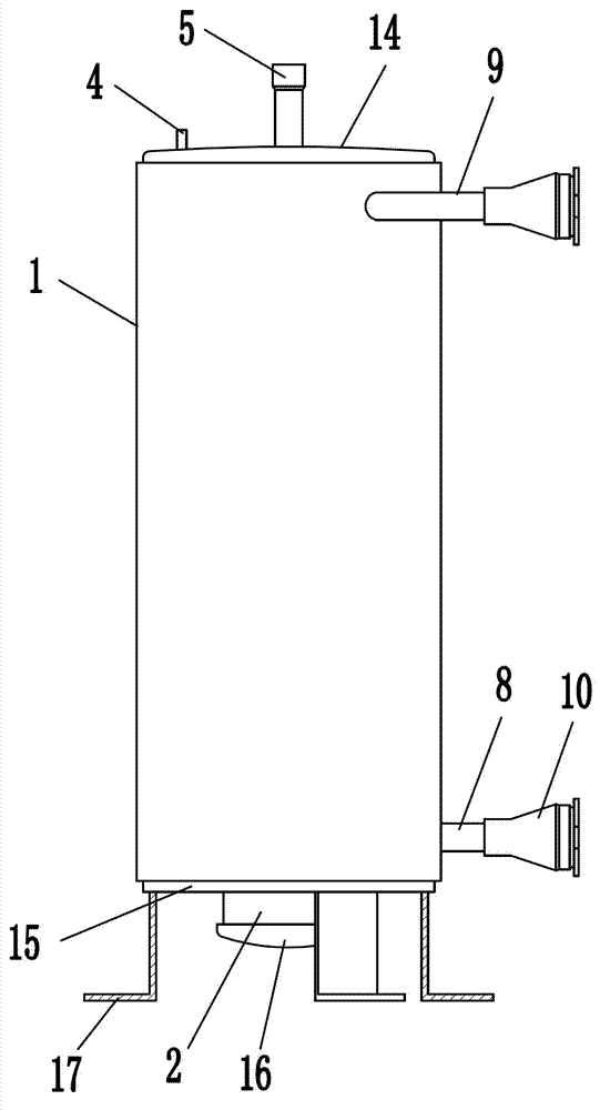
[0027] Embodiment 1: as figure 1 , 2 As shown, a high-efficiency cylindrical heat exchanger includes an outer cylinder 1, and a fixed foot 17 is fixedly installed on the bottom of the outer cylinder 1. The middle part of the outer cylinder 1 is fixed with an inner cylinder 2, and an annular cavity is formed between the inner cylinder 2 and the outer cylinder 1. The upper end cover of the outer cylinder 1 has an upper cover 14, and the lower end cover has a lower cover 15. The lower end of the inner cylinder 2 Covered with a head 16. The bottom end of the inner cylinder 2 has two through holes 3 distributed oppositely, and the inside of the inner cylinder 2 communicates with the outside of the inner cylinder 2 through the through holes 3 . There is a refrigerant inlet 4 on the top of the outer cylinder 1, and a refrigerant outlet 5 on the top of the inner cylinder 2. The refrigerant inlet 4 communicates with the cavity between the outer cylinder 1 and the inner cylinder 2, an...

Embodiment 2

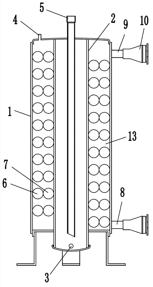
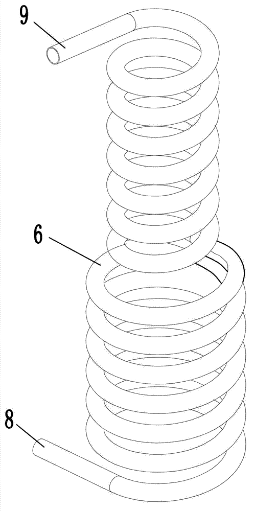
[0033] Embodiment 2: The structure of this embodiment is basically the same as that of Embodiment 1, the difference is that, as Figure 9 As shown, two coil groups are installed in the cavity between the outer cylinder 1 and the inner cylinder 2 , and both coil groups include a first helical coil 6 and a second helical coil 7 . The two sets of coils are connected sequentially, and the two coils are in contact with each other, and the outer coil is in contact with the inner surface of the outer cylinder 1, and the inner coil is in contact with the outer surface of the inner cylinder 2. The part of the coil group between the outer cylinder 1 and the inner cylinder 2 forms a refrigerant channel 13 .

[0034] When the width of the part between the outer cylinder and the inner cylinder is the same, using two coils for each coil group can reduce the cross-sectional diameter of the coil and reduce the distance between the chilled water at the axis of the coil and the refrigerant outs...


PUM


Abstract

The invention relates to a heat exchanger device, in particular to an efficient drum type heat exchanger which comprises an outer drum, wherein an inner drum is arranged in the middle of the outer drum, and the interior of the inner drum is communicated with the exterior of the inner drum. At least one coil pipe set is arranged between the inner wall of the outer drum and the outer wall of the inner drum, and the coil pipe set coils the inner drum in a spiral mode. The coil pipe set comprises a first spiral coil pipe and a second spiral coil pipe, wherein the first spiral coil pipe and the second spiral coil pipe are in the same structure. Each spiral coil pipe is divided into two segments with different coiling diameters, and one end, with a small coiling diameter, of the second spiral coil pipe screws in from one end, with a large coil diameter, of the first spiral coiling pipe, and one end, with a large coiling diameter, of the second spiral coil pipe is coiled on the outer side of one end, with a small coiling diameter, of the first spiral coil pipe. The efficient drum type heat exchanger has the advantages of being capable of effectively improving heat exchange efficiency, strengthening heat exchange effect, and the like.

Description

technical field [0001] The invention relates to a heat exchange device, in particular to a high-efficiency cylinder heat exchanger. Background technique [0002] A single coil is used in the existing cylindrical heat exchanger. When the cross-sectional diameter of the single coil is large, the distance between the chilled water near the axis of the coil and the refrigerant outside the coil is relatively large. , The chilled water has a poor heat transfer effect on the refrigerant. Moreover, due to the large cross-sectional diameter of the coil, in order to ensure the amount of refrigerant outside the coil, the number of turns of the helical coil of the coil should not be made too large. Smaller, thereby reducing the heat transfer effect. When the cross-sectional diameter of a single coil is small, although it is convenient to increase the number of turns of the coil, the small diameter of the coil results in a small amount of frozen water in the coil, and the flow process ...

Claims


Application Information

Patent Timeline
IPC IPC(8): F28D7/02F28D7/04F28F1/24
Inventor 方彦
Owner 方彦
Why Eureka
Try Eureka