
Isolation voltage acquisition circuit

A technology for collecting circuits and isolating voltage, which is applied in the field of isolated voltage sampling circuits, can solve the problems of lower product performance, poor circuit consistency, poor consistency, etc., achieve good accuracy and consistency, ensure consistency and accuracy, and reduce production costs Effect

Inactive Publication Date: 2013-05-22
TIANJIN SANTROLL ELECTRIC AUTOMOBILE TECH CO LTD
View PDF14 Cites 1 Cited by
  • Summary
  • Abstract
  • Description
  • Claims
  • Application Information

AI Technical Summary

Problems solved by technology

[0002] In electronic circuits, for the acquisition of large voltage and high current, it is usually necessary to achieve electrical isolation between the acquisition circuit and the acquired circuit, which requires isolation of the acquisition circuit for acquisition. By isolating the acquisition chip, the acquisition circuit and the acquired circuit are completed The electrical isolation of the power supply terminal and the reference ground terminal of the circuit. The traditional isolation sampling circuit realizes isolation sampling through an analog isolation coupling chip. Since the coupling multiple of the analog isolation coupling chip is not a fixed value but a possible value within a range, the coupling output is also It is a possible value within an interval, rather than a fixed value that can be predicted, so the circuit consistency of the analog isolation coupling chip is poor
In actual production, two products with the same circuit structure using analog coupling chips have different voltage acquisition results. Each product needs to be recalibrated for circuit parameters during the production process to ensure the performance and performance of each product. The consistency of the parameters greatly reduces the production efficiency of the product and also reduces the performance of the product. Due to the poor consistency, the voltage acquisition accuracy of the product is not high, and the cost of the analog isolation acquisition chip is high, which further reflects its The drawbacks in the mass production process, so the traditional isolated acquisition circuit needs to be improved

Method used


Image

  • Isolation voltage acquisition circuit

Examples


Embodiment Construction

[0016] The specific implementation manner of the present invention will be described below in conjunction with accompanying drawing, and the embodiment of the present invention will be described in further detail below in conjunction with accompanying drawing, and the following description about the embodiment of the present invention is only exemplary, not in order to limit the subject matter to be protected of the present invention For the embodiments described in the present invention, there are other changes within the protection scope of the claims, which all belong to the subject matter required to be protected in the present invention.

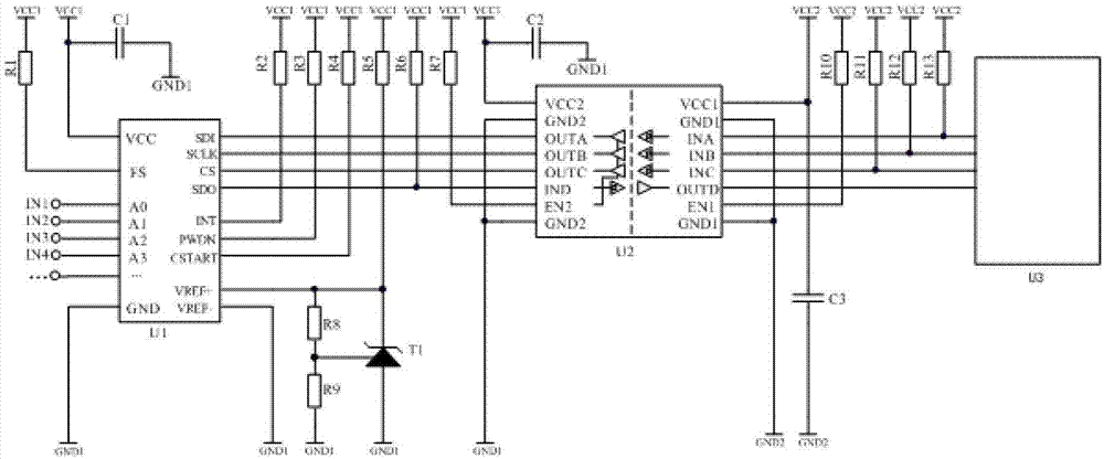
[0017] as attached figure 1 , U1 is an AD conversion chip, U2 is a digital isolation coupling chip, and U3 is a single-chip microcomputer. Several analog signals are connected to the AD conversion chip U1, and the single-chip microcomputer U3 sends instructions to the AD conversion chip U1 through the digital isolation coupling chip U2. ...


PUM


Abstract

The invention discloses an isolation voltage acquisition circuit which comprises an AD (analog-digital) conversion chip U1, a digital isolation coupling chip U2, and a single-chip microcomputer U3. A plurality of analog signals are connected to the AD conversion chip. The single-chip microcomputer U3 sends a command from the digital isolation coupling chip U2 to the AD conversion chip U1. The AD conversion chip U1 selects a certain analog signal to be sampled according to the command, converts the analog signal into a digital signal, and transmits the converted digital signal to the digital isolation coupling chip U2, and the signal is output to the voltage acquisition end single-chip microcomputer U3 for voltage sampling by means of digital isolation coupling. The isolation voltage acquisition circuit high in acquisition precision and uniformity and lower in cost is provided to overcome the defects of poor uniformity, low precision and high cost in the existing analog isolation coupling circuit.

Description

technical field [0001] The invention belongs to the field of voltage acquisition, and in particular relates to an isolated voltage sampling circuit adopting a digital isolation coupling mode. Background technique: [0002] In electronic circuits, for the acquisition of large voltage, high current, etc., it is usually necessary to achieve electrical isolation between the acquisition circuit and the acquired circuit, which requires isolation of the acquisition circuit for acquisition. By isolating the acquisition chip, the acquisition circuit and the acquired The electrical isolation of the power supply end of the circuit and the reference ground end. The traditional isolation sampling circuit realizes isolation sampling through an analog isolation coupling chip. Since the coupling multiple of the analog isolation coupling chip is not a fixed value but a possible value within a range, the coupling output is also is a possible value within an interval, rather than a fixed value...

Claims


Application Information

Patent Timeline
IPC IPC(8): G01R15/14
Inventor 何斌
Owner TIANJIN SANTROLL ELECTRIC AUTOMOBILE TECH CO LTD
Learn More