Piezoelectric ceramic objective driver control method

A piezoelectric ceramic and control method technology, which is applied in the directions of adaptive control, general control system, control/regulation system, etc., can solve the problems of limiting the positioning accuracy of piezoelectric ceramic objective lens driver, rough model parameter setting, slow response speed, etc. Achieve the effect of shortening single positioning time, good dynamic performance and static performance, and fast response speed

Inactive Publication Date: 2013-05-22
GUANGXI UNIV
View PDF3 Cites 16 Cited by
  • Summary
  • Abstract
  • Description
  • Claims
  • Application Information

AI Technical Summary

Problems solved by technology

The early piezoelectric ceramic control methods are mostly proportional integral differential PID control and improved proportional integral differential PID closed-loop control, but due to the inability to establish an accurate model and rough parameter setting, the error is large, the overshoot is large, and the response speed is slow
This greatly limits the further improveme

Method used


Image

  • Piezoelectric ceramic objective driver control method
  • Piezoelectric ceramic objective driver control method
  • Piezoelectric ceramic objective driver control method

Examples


Example Embodiment

[0026] Example 1

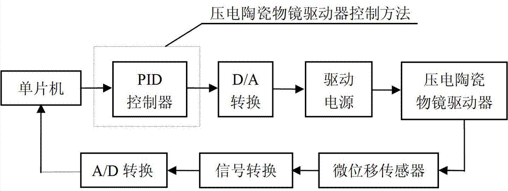
[0027] Such as image 3 As shown, the piezoelectric ceramic objective lens driver control system is mainly composed of a single-chip microcomputer system, a proportional integral derivative PID controller, A / D and D / A conversion, drive power, piezoelectric ceramic objective lens driver and micro-displacement sensor. The described piezoelectric ceramic objective lens driver control method is in the part of the proportional integral derivative PID controller. The described piezoelectric ceramic objective lens driver control method is implemented in the piezoelectric ceramic objective lens driver control system as follows:

[0028] Set the output positioning displacement value of the control system in the single chip microcomputer system, and use it as the input of the proportional integral derivative PID controller in the method of the present invention. The output of the proportional integral derivative PID controller is connected to the input of the D / A converter...


PUM


Abstract

A piezoelectric ceramic objective driver control method includes the steps of separating a process of optimizing initial parameters of a proportion integration differentiation (PID) controller from a process of online adjustment, and configuring the optimized initial parameters to an online control algorithm to accurately control a piezoelectric ceramic objective driver quickly. In an off-line state, global optimization of the initial parameters of the PID controller is completed by a genetic algorithm in advance, the optimized initial parameters are configured into a process of online fuzzy PID control and are subjected to online feedback and real-time control, and accordingly, the piezoelectric ceramic objective driver is subjected to micro-stepping location under drive. By the piezoelectric ceramic objective driver control method, the piezoelectric ceramic objective driver can be controlled accurately and is low in output overshot, high in stability and response speed.

Description

1. Technical field [0001] The invention relates to the technical field of precision control of a piezoelectric ceramic driver, in particular to a control method for a piezoelectric ceramic objective lens driver. 2. Background technology [0002] Digital confocal microscopy technology is a technology that emerged in the 1990s based on biological optical microscopy, using optical sectioning technology and image restoration methods to obtain high-resolution sequential biological microscopic images. This technology relies on the relative stepwise micro-displacement of the objective lens and the stage driven by a micro-displacement drive element to perform sequential slice image acquisition of biological cells. Therefore, the driving quality of the micro-displacement driving element is the key to the quality of the collected image. At present, there are many kinds of micro-displacement driving components used in practice, and the piezoelectric ceramic driver has become a micro-d...

Claims


Application Information

Patent Timeline
IPC IPC(8): G05B13/02
Inventor 陈华董钊明林广升聂雄
Owner GUANGXI UNIV
Why Eureka
Try Eureka