Pipe and condensate boundary film collection and drainage device for installation in said pipe

A technology of exporting device and condensate, applied in the field of pipeline, can solve the problems of weight, unable to reach the minimum speed of condensate, small outlet, etc.

Active Publication Date: 2013-05-22
MUNTERS EUROFORM GMBH
View PDF1 Cites 0 Cited by
  • Summary
  • Abstract
  • Description
  • Claims
  • Application Information

AI Technical Summary

Problems solved by technology

Since the path through which the part of the gas flows in the film collecting and discharging device at the edge of the condensate has only a small width compared to the pipe diameter, a gas blockage area can form in this area, so that the required flow rate for the condensate cannot be achieved The minimum velocity of the derivation, so that the condensate edge film is at least not completely carried away by part of the gas flow, but at least part of it is transported out of the wet chimney over the edge film trap and the central gas flow, so that the preset edge film The trap works only partially or not at all
This "clogging effect" is also exacerbated by the small exit of the gas flow out of the edge membrane trap and the multiple reversals of the gas flow in the edge membrane trap

Method used


Image

  • Pipe and condensate boundary film collection and drainage device for installation in said pipe
  • Pipe and condensate boundary film collection and drainage device for installation in said pipe
  • Pipe and condensate boundary film collection and drainage device for installation in said pipe

Examples


Embodiment Construction

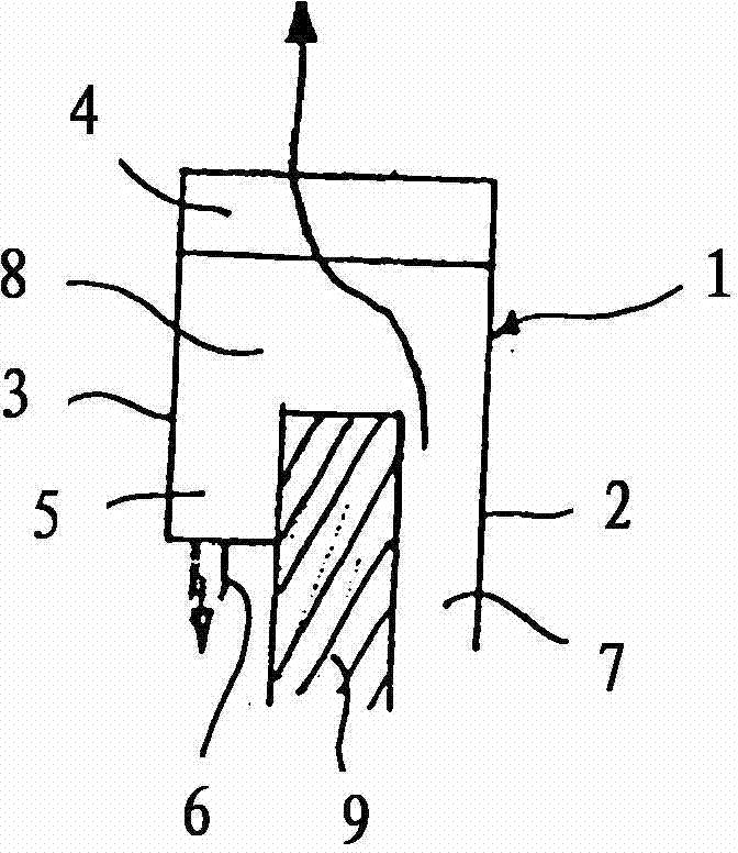
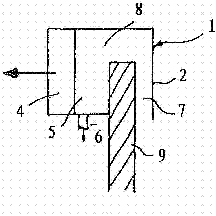
[0033] exist figure 1 The end wall of the wet chimney mouth is marked with 9 in the schematic vertical cross-sectional view of . The condensate edge film collection and discharge device 1 is schematically shown at the wet chimney mouth. The device has a separating element 2 which is annular and extends from the outside to the inside of the chimney. An annular space 7 is formed between the separating element 2 and the chimney wall 9 in such a way that it extends to a larger annular space 8 between the annular boundary wall 3 and the separating element 2 . figure 1 The gas flow direction is from bottom to top. A droplet separator in the form of an annular separator 4 in the direction of gas flow, likewise located between the separating element 1 and the dividing wall 3 , is arranged downstream of the annular space 8 . A condensate collection annular space 5 with a condensate drain 6 is located on the outside of the chimney wall 9 below the annular space 8 .
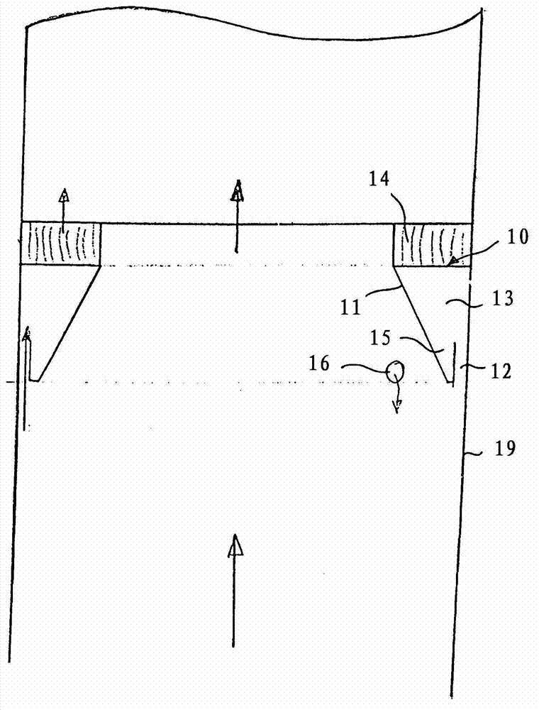
[0034] The cond...


PUM


Abstract

The invention describes a pipe for conducting or discharging wet gases, and a condensate boundary film collection and drainage device for installation in a pipe of said type. The pipe is designed in particular as a wet flue. The condensate boundary film collection and drainage device is arranged at the mouth of the pipe or in the interior of the pipe. Said condensate boundary film collection and drainage device has a droplet separator designed preferably as an annular separator. Effective removal of the condensate boundary film formed is attained in this way.

Description

technical field [0001] The invention relates to a pipeline for the conduction or discharge of moist gas, in particular for the conduction or discharge of wet-washed waste gas, with a condensate edge film collection and discharge device, the condensate edge film collection and discharge device has Separation element and corresponding condensate discharge device placed in the inner edge area of ​​the pipe for separating part of the air flow from the air flow flowing through the pipe. [0002] The invention also relates to a condensate edge film collection and discharge device for construction in a device for the conduction or discharge of moist gas. Background technique [0003] When passing or conducting moist gas through a pipe, the gas flow comes into contact with the relatively cool pipe wall to form condensate, which accumulates on the pipe inner wall in the form of a marginal film of condensate. This edge film of condensate is co-entrained or carried away by the movemen...

Claims


Application Information

Patent Timeline
Patent Type & Authority Applications(China)
IPC IPC(8): B01D53/26B01D45/08
CPCB01D45/08B01D45/06B01D53/263B01D5/0027
Inventor M·詹森
Owner MUNTERS EUROFORM GMBH
Why Eureka
Try Eureka