Apparatus for tightening threaded fasteners

A technology of threaded fasteners and fasteners, which is applied in the direction of threaded fasteners, locking fasteners, screws, etc., can solve the problem of not being able to carry high torque values, and achieve effective and uniform distribution, small mass, The effect of high torsional strength

Active Publication Date: 2013-05-22
JETYD CORP
View PDF12 Cites 9 Cited by
  • Summary
  • Abstract
  • Description
  • Claims
  • Application Information

AI Technical Summary

Problems solved by technology

Therefore, higher moment values ​​cannot be carried by internal structures in the top surface...

Method used


Image

  • Apparatus for tightening threaded fasteners
  • Apparatus for tightening threaded fasteners
  • Apparatus for tightening threaded fasteners

Examples


Embodiment Construction

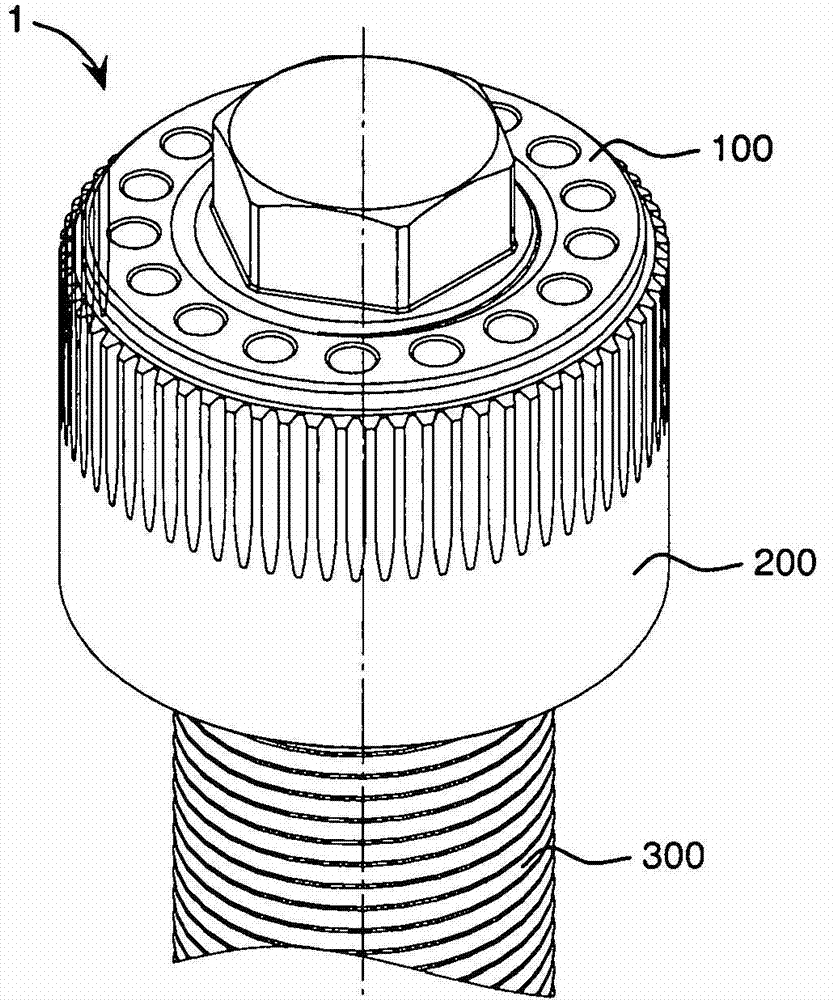
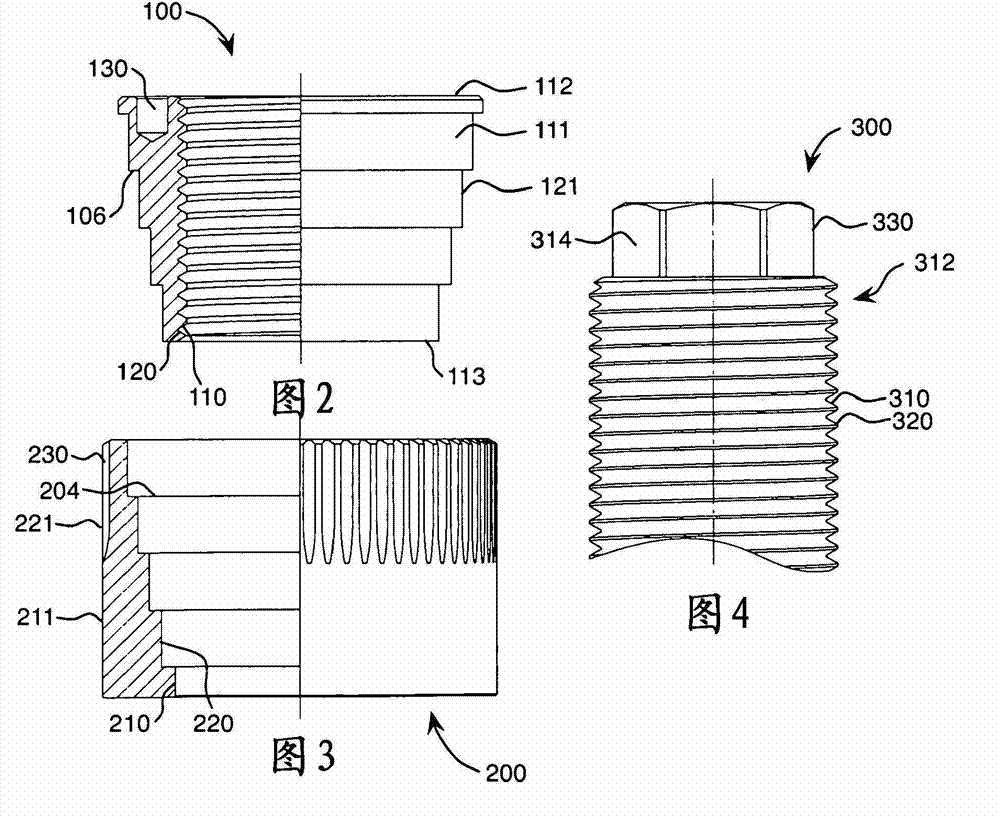
[0034] For example reference Figure 1-4 , shows a device 1 - a stepped conical fastener assembly according to an embodiment of the present invention. The device 1 has an inner sleeve part 100 and an outer sleeve part 200 and is for example for a stud 300 . The inner sleeve member 100 may be rotatably threadedly engaged with the stud 300; rotatably tapered with the outer sleeve member 200; and non-rotatably engaged with the active portion of the torque input device. The outer sleeve member 200 may be in non-rotatable engagement with the reaction portion of the torque input device; and in rotatable conical engagement with the inner sleeve member 100 . When rotated by the active part of the torque input, the inner sleeve part 100 applies a load to the stud 300 in order to close the connection (not shown).

[0035] The inner sleeve part 100 is an annular body, such as figure 1 and 2 shown in and formed as a sleeve. It has an inner surface 110 with an inner helical threading ...


PUM


Abstract

According to a first aspect of the invention we provide an apparatus (1) for use with a threaded fastener including: -an inner sleeve member (100) having an internal surface threadedly engagable with the fastener and a tapered external surface; and an outer sleeve member (200) having an inversely tapered internal surface rotatably engagable with the tapered external surface of the inner sleeve member. Advantageously, the invention allows for an increased load bearing surface area between the inner sleeve member (100), which is clamped, and the outer sleeve members (200) without increasing the overall diameter of the apparatus (1) 6; a three dimensional load bearing surface area rather than a conventional two dimensional plane; more efficiently and evenly distributed load stress distribution over the load bearing surface area; higher torsion strength; and apparatus with lower mass, dimensions and volume.

Description

[0001] Cross References to Related Applications [0002] This application is a continuation of co-pending U.S. Patent Application No. 61 / 370015, filed August 2, 2010, and entitled "Conical Geometry for Torsion Coupling During Bolting" , and this application is a continuation of co-pending PCT International Application No. PCT / IB2011 / 002658, filed August 2, 2011, entitled "Apparatus For Tightening Threaded Fasteners", the entire contents of these two documents are incorporated into this application as a reference. [0003] The new technology disclosed in this application improves upon the technology disclosed in the following commonly-owned issued patent and patent application: U.S. Patent No. 5,137,408, filed December 3, 1991, entitled "Fastening Device"; U.S. Patent No. 5318397, filed on May 7, 1992, titled "Mechanical Tensioner"; U.S. Patent No. 5622465, filed on April 26, 1996, titled "Lock Nut"; U.S. Patent No. 5640749, filed on June 13, 1995, titled "Method Of And Device ...

Claims


Application Information

Patent Timeline
IPC IPC(8): F16B31/02F16B39/36
CPCF16B31/027B25B15/008B25B23/0085F16B31/02F16B39/36B25B13/30B25B23/14F16B37/00F16B37/08
Inventor M·F·多兰
Owner JETYD CORP
Why Eureka
Try Eureka