Light emitting module assembly for radiator and lamp

A light-emitting module and heat sink technology, which is applied to semiconductor devices, light sources, electric light sources, etc. of light-emitting elements, and can solve the problem of large amount of heat sink materials

Inactive Publication Date: 2017-03-01
ZUMTOBEL LIGHTING INC
View PDF3 Cites 0 Cited by
  • Summary
  • Abstract
  • Description
  • Claims
  • Application Information

AI Technical Summary

Problems solved by technology

[0003] However, the structure of the heat dissipation fins makes th

Method used


Image

  • Light emitting module assembly for radiator and lamp
  • Light emitting module assembly for radiator and lamp
  • Light emitting module assembly for radiator and lamp

Examples


Embodiment Construction

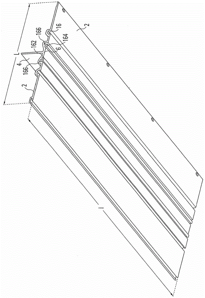
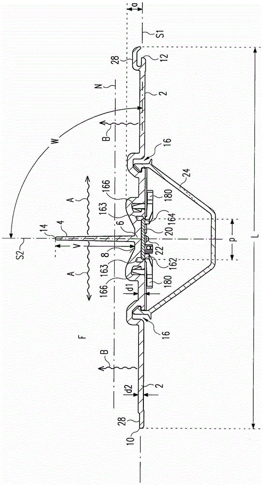
[0028] figure 1 A schematic perspective view of an embodiment of a heat sink according to the invention for a lamp is shown, figure 2 A corresponding cross-sectional view is shown. At this time, at figure 2 In addition to the heat sink, other components of the lamp that will be mentioned below are also shown.

[0029] The cooling body has an at least very approximately plate-shaped first section 2 and an at least very approximately plate-shaped second section 4 . "At least very approximately plate-shaped" here means that a plane is defined by the shape of the relevant segment and that the maximum distance of the surface of the segment from this plane is not greater than the smaller extent of the extent of the segment in that plane. Small percentages such as 10% or 5%. This will combine figure 2 Let's take an example to explain in detail. A plane S1 is defined by the plate-like structure of the first section 2 , which is referred to as the plane occupied by the largest...


PUM


Abstract

The invention relates to a cooling body for a light, said body comprising a first segment (2) which is flat at least on the first edges, and a second segment (4) which is flat at least in the first edges. The second segment (4) is directly connected to the first segment (2) and in such a manner that said second segment (4), when the first segment (2) is oriented horizontally, extends vertically upwards at least essentially from a central area (6) of the first segment (2), and also measured from a surface area (8) of the first segment (2), oriented upwards, about a vertical extension (V). According to the invention, the cooling body is designed in such a manner that it, when seen in the vertical through the first segment (2) and the second segment (4), it does not have any other parts other than the second segment (4) which is located above a level (TV) which is fixed by half of the vertical extension (V), preferably by a quarter of the vertical extension (V). Said embodiment enables relatively large cooling body surfaces which allow, in a first line, the heat to be distributed by radiation, to be produced. Due to the fact that there are no other parts of the cooling body in the area which is lateral about the second segment (4), heat can be radiated (Ä) from the surface areas of the second segments (4) in a practically unhindered manner. In particular, said lateral heat distribution is not hindered by cooling ribs or other additional parts. Also, the heat radiation from the first segment (2) upwards can also be carried out unhindered. The invention also relates to a light module arrangement, at least one LED (2) being arranged on a cooling body of said type and to a correspondingly equipped lamp.

Description

technical field [0001] The present invention relates to radiators. The present invention also relates to a light-emitting module assembly for a lamp with such a radiator and a lamp with such a radiator or such a light-emitting module assembly. Background technique [0002] Heat sinks with a horizontal base, from which a plurality of plate-shaped cooling fins protrude upwards, are known from the prior art. Because of this structure, the heat sink surface is very large, thereby allowing the heat sink to effectively dissipate heat to the surrounding air. [0003] However, the structure of the heat dissipation fins makes the material consumption of the heat dissipation body relatively large. Contents of the invention [0004] The object of the present invention is to provide an improved cooling body, in particular the cooling body should be produced efficiently with a low amount of material. In addition, a light module assembly with such a heat sink and an improved lamp wit...

Claims


Application Information

Patent Timeline
IPC IPC(8): F21S4/00F21V15/01F21V29/503F21V29/70F21Y115/10
CPCF21S4/28F21V15/013F21V29/507F21V29/74F21Y2103/10F21Y2115/10
Inventor W·巴赫特贝恩德·瓦尔泽M·斯皮格尔W·卢夫
Owner ZUMTOBEL LIGHTING INC
Why Eureka
Try Eureka