Fuel evaporation configuration structure of straddle type motorized cart

A technology of motorized two-wheeled vehicle and configuration structure, which is applied to the panniers, gasoline drums, bicycle accessories and other directions of bicycles, can solve the problems of complex confusion, the impact of the compactness of the locomotive, and the narrow space, so as to achieve a reasonable and concise layout and improve riding performance. Ride comfort and compact body

Active Publication Date: 2013-05-29
JIANGMEN DACHANGJIANG GROUP CO LTD
View PDF4 Cites 3 Cited by
  • Summary
  • Abstract
  • Description
  • Claims
  • Application Information

AI Technical Summary

Problems solved by technology

At present, for models with fuel tank and tool box arranged under the seat, the conventional layout of the fuel evaporation system is to arrange the carbon canister on the side of the fuel tank or the rear of the fuel tank and tool box. The impact of the vehicle is relatively large, especially for the double-tube rear frame. Due to the large distance between the left and right pair of seat side bars (that is, the left and right rear frame) along the vehicle width direction, this leads to the The space on the side of the fuel tank on the outside of the side bar along the width direction of the vehicle is narrow. If the carbon canister is placed on the side of the fuel tank, considering the need to avoid the interference of the side bar of the seat, the only way to set aside the carbon canister is to set the fuel tank on the fuel tank. The concave part of the tank or the volume of the tool box is greatly reduced to reserve the space for the canister installation, which will inevitably lead to problems such as smaller fuel tank volume, insufficient fuel tank capacity, or narrow space in the tool box. If the original fuel tank and The struc

Method used


Image

  • Fuel evaporation configuration structure of straddle type motorized cart
  • Fuel evaporation configuration structure of straddle type motorized cart
  • Fuel evaporation configuration structure of straddle type motorized cart

Examples


Embodiment Construction

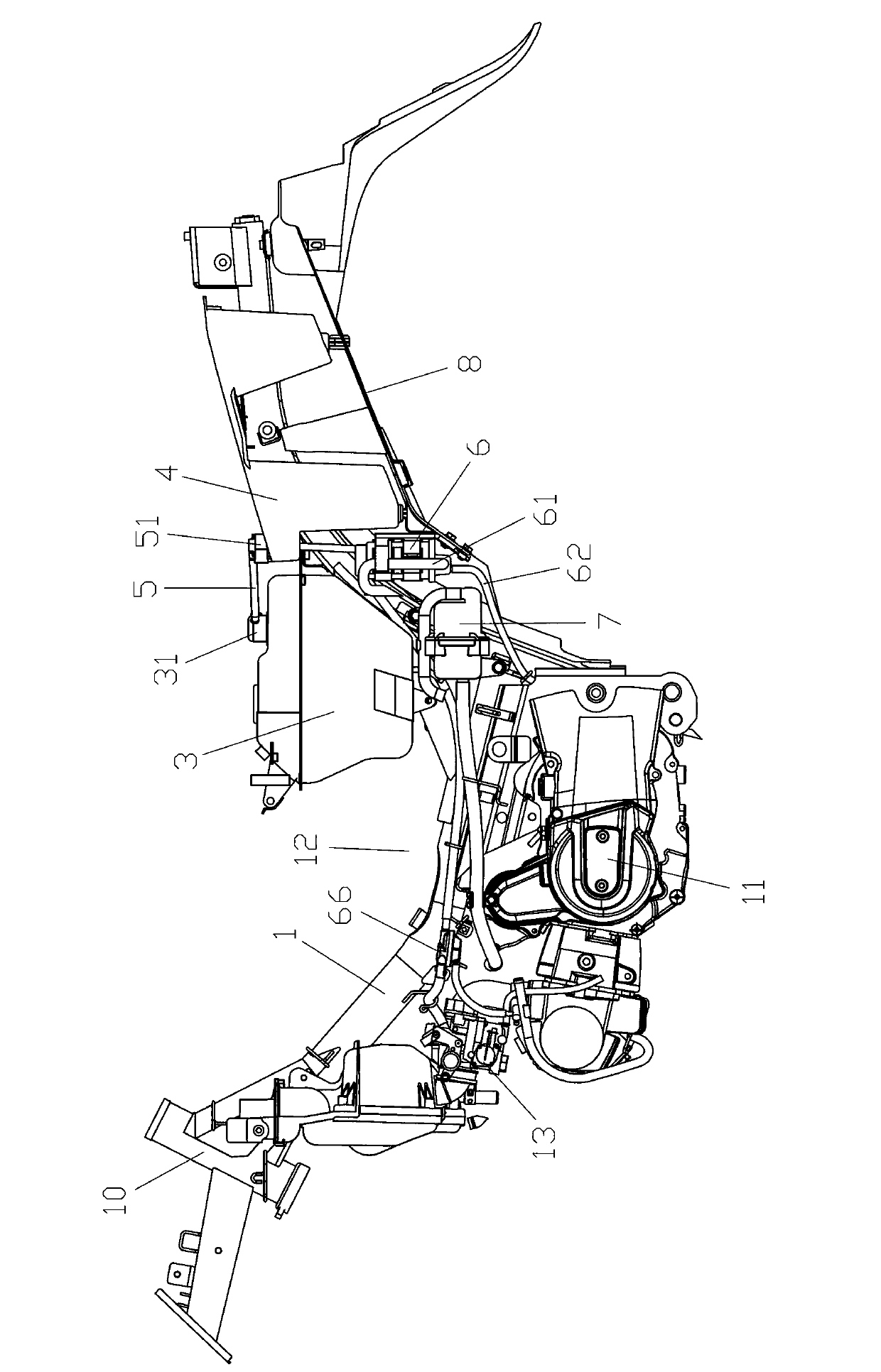
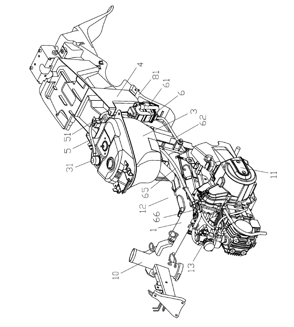
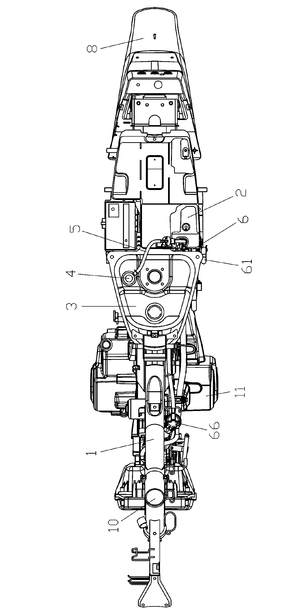
[0021] The present invention will be described in further detail below in conjunction with the accompanying drawings and embodiments. In the following descriptions of the preferred embodiments of the present invention, unless otherwise stated, the descriptions in the directions of front, rear, left, right, and up and down all refer to the forward direction of the locomotive.

[0022] refer to Figure 1~Figure 5 , the fuel evaporation configuration structure of the straddle-type motorcycle of the present invention comprises a head pipe 10, which is connected with a main frame 1 extending backward and downward for suspending the engine 11 on the head pipe 10, the main frame The rear end of 1 is connected with a rear frame 2 extending rearward and upward, and a concave straddle 12 is formed between the main frame 1 and the rear frame 2, which is convenient for the rider to step over the vehicle body with one foot. A fuel tank 3 at least partially overlapped with the straddle por...


PUM


Abstract

The invention discloses a fuel evaporation configuration structure of a straddle type motorized cart. The fuel evaporation configuration structure of the straddle type motorized cart comprises a head tube, a main cart frame, and a back cart frame, a concave-shaped straddle part which facilitates riders to stride a cart body in one foot is formed between the main cart frame and the back cart frame, a fuel tank which is at least partly overlapped with the concave-shaped straddle part and a tool box on the back position of the fuel box are arranged on the back cart frame, the fuel tank and the tool box are arranged below a cart seat, an oil-gas separator on the fuel tank is connected with a carbon tank through an absorption tube, the back cart frame is a single beam which an independent cart frame stretches to a back top position, the carbon tank is arranged inside space between the fuel tank and the tool box of the cart body, the carbon tank is vertically arranged, and at least partial carbon tank is overlapped with the fuel tank when the cart is overlooked. The fuel evaporation configuration structure of the straddle type motorized cart ensures capacity of the fuel tank and the tool box and compact cart body. Additional protective components are unnecessary due to the fact that the carbon tank is protected by the fuel tank, the tool box, and a cart body cover.

Description

technical field [0001] The invention relates to the optimization of the fuel evaporation arrangement structure of a straddle type motor two-wheel vehicle. Background technique [0002] Existing motor two-wheeled vehicle is all provided with fuel evaporation system usually in order to introduce fuel vapor into engine combustion and prevent fuel vapor from volatilizing into the atmosphere. At present, for models with fuel tank and tool box arranged under the seat, the conventional layout of the fuel evaporation system is to arrange the carbon canister on the side of the fuel tank or the rear of the fuel tank and tool box. The impact of the vehicle is relatively large, especially for the double-tube rear frame. Due to the large distance between the left and right pair of seat side bars (that is, the left and right rear frame) along the vehicle width direction, this leads to the The space on the side of the fuel tank on the outside of the side bar along the width direction of t...

Claims


Application Information

Patent Timeline
IPC IPC(8): B62J35/00B62J37/00B62J9/02B62J9/40
Inventor 向友森邹志民
Owner JIANGMEN DACHANGJIANG GROUP CO LTD
Why Eureka
Try Eureka