A process method for aligning shafts using laser cladding technology

A technology of laser cladding and process method, which is applied in the field of shaft alignment, can solve the problems of inaccurate manual setting of bending amount, affect the surface structure and performance of parts, and difficult to control the alignment process, so as to save the man-hours of transportation and disassembly , easy to guide, small processing effect

Active Publication Date: 2016-05-04
SHENYANG DALU LASER TECH
View PDF6 Cites 0 Cited by
  • Summary
  • Abstract
  • Description
  • Claims
  • Application Information

AI Technical Summary

Problems solved by technology

In the straightening process of heating method and percussion method, the straightening process is difficult to control and cannot be quantified. The straightening work largely depends on the experience of the workers. At the same time, flame heating will enlarge the heat-affected zone and affect the surface of the parts. organizational performance
The use of pressure straightening and bending requires manual inspection, and the manual setting of the bending amount is not accurate enough and the efficiency is low. The straightening accuracy is determined entirely by the operator's experience.

Method used


Image

  • A process method for aligning shafts using laser cladding technology
  • A process method for aligning shafts using laser cladding technology

Examples


Embodiment 1

[0016] Example 1 Shaft calibration of a fan in a company: the diameter of the impeller is 3000mm, the length of the shaft is 5000mm, and the maximum bending amount is 0.28mm. The cause of the bending is the dynamic and static imbalance of the impeller. At the same time, the main shaft diameter, the shaft diameter where the coupling is installed, and the impeller installation are all worn out, and repairs are required after the shaft is adjusted.

[0017] The process steps are as follows.

[0018] 1) Descale the bent shaft, clean the shaft diameter, and then remove the impeller to disassemble the impeller and the shaft, color the shaft as a whole, test the hardness, and take pictures of the damaged parts for archiving.

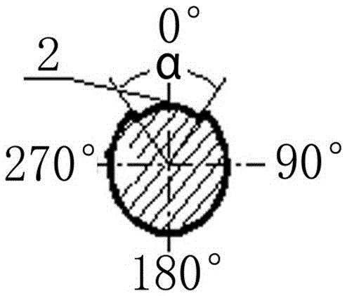
[0019] 2) Place the shaft on the grinding machine for size detection and shaft runout detection, and record the maximum runout value, bending position and bending high point phase.

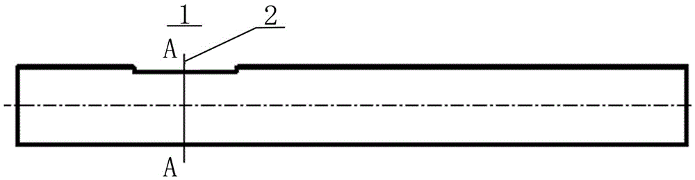
[0020] 3) Process the cladding groove at the high point where the φ300×110 fa...

Embodiment 2

[0025] Example 2 A company’s TRT shaft alignment: the rotation diameter of the main shaft blade is 1400mm, the shaft length is 4500mm, and the maximum bending amount is 3.4mm. The parts of the shaft along the shaft length are severely worn, and the shaft alignment and remanufacturing engineering maintenance are urgently needed.

[0026] The process steps are as follows.

[0027] 1) Descale the bent shaft, clean the shaft diameter, and then remove the impeller to disassemble the impeller and the shaft, color the shaft as a whole, test the hardness, and take pictures of the damaged parts for archiving.

[0028] 2) Place the shaft on the grinding machine for size detection and shaft runout detection, and record the maximum runout value, bending position and bending high point phase.

[0029] 3) Process the cladding groove at the high point of the seal around φ290×500, the areas are: 220×200×6mm; 150×135×6mm, the rounded corners are required to be smooth, and there are grooves on ...


PUM

PropertyMeasurementUnit
diameteraaaaaaaaaa

Abstract

A technological method for straightening a shaft by a laser cladding technology includes 1), detecting a bent portion and a bent direction of a shaft part; 2), machining a cladding groove at a high point of the bent position of the shaft or a machinable high point of the shaft; (3), straightening the cladding groove by means of laser cladding; 4), removing residual stress on the surface which is subjected to laser cladding after the shaft part is thoroughly cooled; 5), detecting a jumping value of the shaft again to determine whether the shaft needs to be subjected to laser cladding again or not; and 6), machining and polishing the surface which is subjected to laser cladding to guarantee the precision of the shaft after the shaft is repaired. The technological method has the advantages that contact machining is omitted, abrasion of tools is prevented, laser beams can be guided and focused easily and are high in energy density, the machining speed is high, a heat affected zone is small, follow-up machining workload is low, the method can be used with a numerical control system easily to realize automation, and particularly, the shortcoming that deformation of a shaft cannot be precisely controlled by means of changing technological parameters to straighten the shaft by laser in the prior art is overcome.

Description

technical field [0001] The invention relates to a shaft calibration method, in particular to a shaft calibration process using laser cladding technology. Background technique [0002] Shaft parts and shafting components are important components of mechanical devices, generally as components that transmit force, and usually bear bending loads, torsional loads or combined bending and torsion loads. There are three main reasons for the bending of the shaft. One is the cumulative bending of the shaft after long-term use, and the shaft runout value is 0.03-0.05mm. Compressive stress is generated due to the limitation of the lower temperature part. If the compressive stress is greater than the yield limit at this temperature, permanent deformation occurs, and the metal in the heated part is compressed and shortened. When it is completely cooled, the axis bends and deforms in the opposite direction. , the friction scar is on the concave side of the shaft, forming a permanent bendi...

Claims


Application Information

Patent Timeline
Patent Type & Authority Patents(China)
IPC IPC(8): C23C24/10
Inventor 陈江郑晖韩志仁
Owner SHENYANG DALU LASER TECH
Why Eureka
Try Eureka