Water pump mounting structure in internal combustion engine

A mounting structure, internal combustion engine technology, applied in the direction of engine cooling, mechanical equipment, engine components, etc., can solve the problems of poor assembly, difficulty in maintaining sealing, and water pump housing not being firmly fixed, etc.

Active Publication Date: 2015-04-22
HONDA MOTOR CO LTD
View PDF3 Cites 0 Cited by
  • Summary
  • Abstract
  • Description
  • Claims
  • Application Information

AI Technical Summary

Problems solved by technology

[0008] In Patent Document 1, the upper discharge connecting pipe of the water pump housing is inserted into the opening of the side wall mounting surface of the internal combustion engine body, and the lower mounting bracket is fastened to the side wall mounting surface of the internal combustion engine body at only one point by means of bolts. Therefore, the lower part is partially fastened, and the whole of the water pump housing is not firmly fixed
[0009] Since the upper part of the water pump housing is not fastened to the side wall of the internal combustion engine body, it is difficult to maintain the sealing performance when the upper discharge connecting pipe should be inserted into the opening of the side wall mounting surface in a liquid-tight manner.
[0010] In addition, since a heavy object such as a pulley or a power steering pump is attached to the pump cover side of the water pump case, it is easy to cause positional deviation as follows, which deteriorates assembly: The fastening bolt fixed to the side wall of the main body of the internal combustion engine rotates as the center

Method used


Image

  • Water pump mounting structure in internal combustion engine
  • Water pump mounting structure in internal combustion engine
  • Water pump mounting structure in internal combustion engine

Examples


Embodiment Construction

[0035] Below, based on Figure 1 to Figure 11 An embodiment of the present invention will be described.

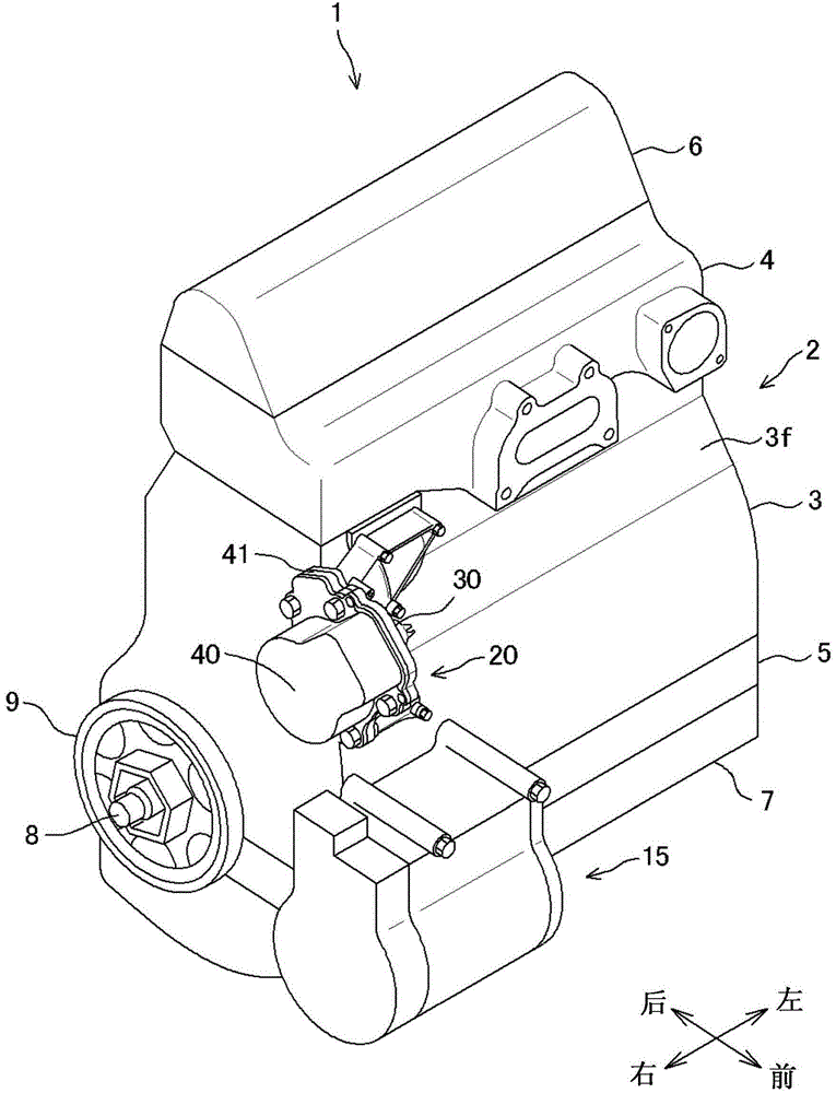
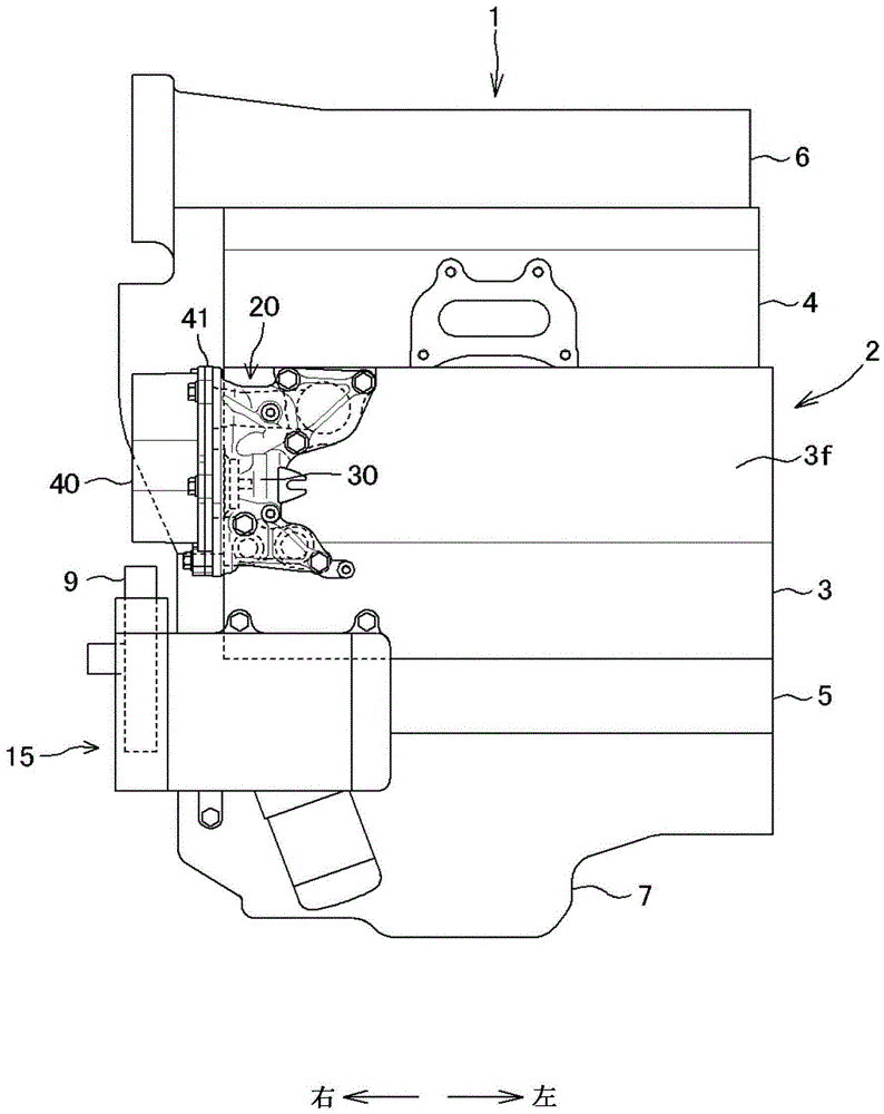
[0036] Such as figure 1 with figure 2 As shown, the internal combustion engine 1 of the present embodiment is an in-line 4-cylinder 4-stroke water-cooled internal combustion engine, and the crankshaft 8 is horizontally mounted on the vehicle so as to point in the left-right direction.

[0037] In this specification, the front, back, left, and right are defined based on the vehicle.

[0038] The internal combustion engine main body 2 of the internal combustion engine 1 is configured such that the lower housing 5 pivotally supports the crankshaft 8 so as to sandwich the crankshaft 8, and the lower housing 5 is joined to the lower part of the cylinder block 3 in which cylinders are arranged in the left-right direction. A cylinder head 4 is overlapped above the body 3, a cylinder head cover 6 is covered on the cylinder head 4, and an oil pan 7 is joined below the lower housing 5.

[...


PUM


Abstract

A water pump mounting structure includes a water pump cover and a water pump housing. The water pump housing includes an upper extending portion and a lower extending portion. The upper extending portion includes a first upper fastening portion and a second upper fastening portion. The second upper fastening portion is provided between the first upper fastening portion and a pump driving shaft. The lower extending portion includes a first lower fastening portion and a second lower fastening portion. The second lower fastening portion is provided between the first lower fastening portion and the pump driving shaft.

Description

Technical field [0001] The invention relates to a mounting structure for mounting a water pump on the internal combustion engine body of a water-cooled internal combustion engine. Background technique [0002] Various structures are proposed as follows: a water pump cover that is equipped with an actuator and supports the pump drive shaft and a water pump housing that accommodates the impeller are combined to form a water pump, and the water pump is detachably mounted on the internal combustion engine of the internal combustion engine Main body (for example, refer to Patent Document 1). [0003] Patent Document 1: Japanese Patent Laid-Open No. 04-012134 [0004] Patent Document 1 discloses a structure in which the power steering pump is integrally provided with the water pump to be driven by a common pump drive shaft, and the water pump housing and the power steering pump housing that house the impeller sandwich the common pump The covers are combined, and a pulley as a common actu...

Claims


Application Information

Patent Timeline
Patent Type & Authority Patents(China)
IPC IPC(8): F02B67/06
CPCF02F7/0073F01P5/10
Inventor 板仓纯
Owner HONDA MOTOR CO LTD
Why Eureka
Try Eureka