Sharkskin imitation streamline groove end face mechanical sealing structure

A technology of end face mechanical seal and sealing structure, applied in the direction of engine seal, mechanical equipment, engine components, etc., can solve the problems of limited use range, starting performance or dynamic pressure effect and unsatisfactory air film bearing capacity, etc., to improve starting Performance, obvious effect of reducing pressure and increasing resistance, and good lubricating effect

Active Publication Date: 2013-05-29
ZHEJIANG UNIV OF TECH
View PDF15 Cites 9 Cited by
  • Summary
  • Abstract
  • Description
  • Claims
  • Application Information

AI Technical Summary

Problems solved by technology

Although these fluid type groove end face seals have low friction power consumption and excellent stability, the unsa

Method used


Image

  • Sharkskin imitation streamline groove end face mechanical sealing structure
  • Sharkskin imitation streamline groove end face mechanical sealing structure
  • Sharkskin imitation streamline groove end face mechanical sealing structure

Examples


Embodiment 1

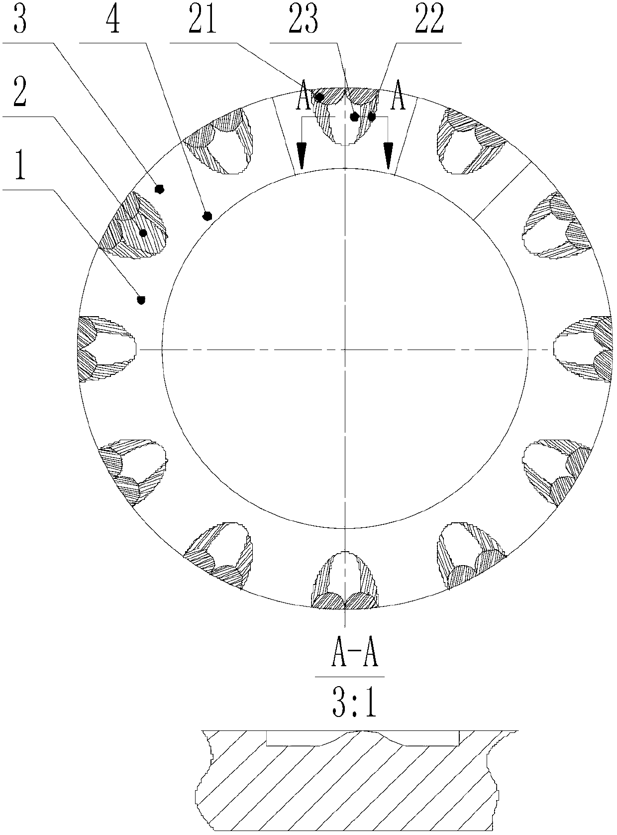
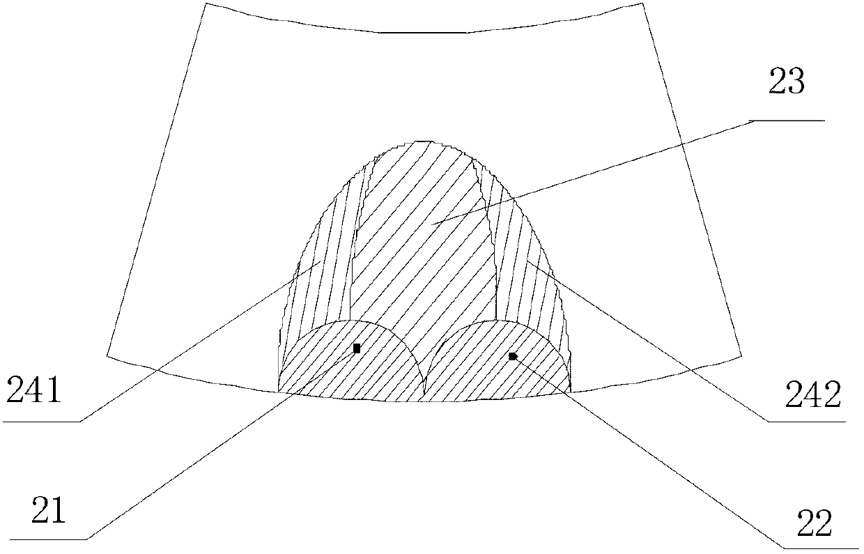
[0028] refer to figure 1 , figure 2 with image 3 , a streamlined groove end face mechanical seal structure imitating the wrinkled shape of the shark skin surface, which includes a dynamic ring and a static ring of the mechanical seal, and at least one seal ring in the dynamic ring or the static ring is provided with multiple sets of edges on the end face 1 Shark-skin-like streamlined grooves 2 uniformly distributed in the circumferential direction, each group of fluid-shaped grooves consists of a left circular arc groove 21, a right circular arc groove 22, rib ridge-shaped bosses 23 along the downstream direction in the groove 2, and its connection with the groove The transition part 241 and 242 between the outer contour lines of 2 form a streamlined groove similar to the wrinkled shape of the surface of the shark skin, which is referred to as the imitation shark skin streamlined groove for short. The imitation sharkskin streamlined groove is arranged on the high-pressure ...

Embodiment 2

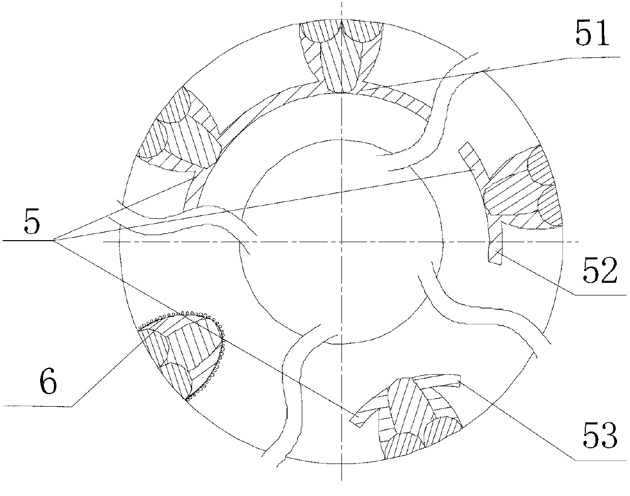
[0039] refer to Figure 4 The difference between this embodiment and the first embodiment is that the downstream end of the imitation sharkskin streamlined groove is connected with other grooves 5 or holes 6, so as to improve the uniformity of pressure distribution in the circumferential direction of the end surface where the root of the groove is located and in the vicinity thereof , Enhance the hydrodynamic pressure effect, improve the rigidity of the fluid film, improve the start-up characteristics of the seal, the ability to operate at low speed and low pressure, and the anti-wear ability of the end face. Described type groove 5 can be circular groove 51, circular arc groove 52 or 53 etc. type line groove, and the width and depth of type groove are respectively w a and h a , the value range is: w a =0.5~2.0mm, h a =h g / 5~h g / 2, where h g Is the depth of the imitation sharkskin streamlined groove; The type hole 6 is a millimeter-level regular cross-section hole, and...

Embodiment 3

[0041] refer to Figure 5 The difference between this embodiment and the first embodiment is that the left circular arc groove 21 and the right circular arc groove 22 present a converging stepped structure with a deep upstream and a shallow downstream. The convergent fluid type groove can be one step, two steps or multiple steps, but in order to control the processing cost, under the premise of meeting a certain cost performance, generally two or three steps are better, the convergent type left The minimum depth of the downstream side of the circular arc groove or the right circular arc groove should meet: when sealing liquid medium, not less than 0.25mm, when sealing gas medium, not less than 1.0μm; in addition, in sealing stability and end surface lubricity requirements are higher In some cases, a convergent inclined step structure may also be used, and the inclination angle of the inclined step is 2-10 degrees. Shark-skin-like streamlined groove end face mechanical seal wi...


PUM


Abstract

Disclosed is a streamline groove end face mechanical sealing structure imitating a creased appearance of the surface of sharkskin. The streamline groove end face mechanical sealing structure comprises two mechanical sealing rings, namely a moving ring and a static ring, plural groups of streamline grooves imitating the creased appearance of the surface of the sharkskin and arranged along the peripheral direction are arranged at least one end face of the sealing rings of the moving ring and the static ring. Each biomimetic groove comprises a left circular groove and a right circular groove, a convex platform along the pressure drop direction in the groove and transitional parts between two sides of the convex platform and an outer contour line of the groove, so that the streamline grooves, namely sharkskin imitation streamline grooves, with the appearance imitating the creased surface of the sharkskin are formed. The sharkskin imitation streamline grooves are arranged on a high pressure side of an end face medium, namely an upper stream. The whole outlines of the sharkskin imitation streamline grooves are in a contracting shape along the pressure drop direction. The sharkskin imitation streamline grooves are arranged to form a groove annular belt along the circumference of the end face, and a plane annular belt area without grooves on the outer end face other than the groove annular belt is a sealing dam.

Description

Technical field: [0001] The invention belongs to a non-contact end face sealing device of a rotating machine, which is suitable for the shaft end sealing device of a rotating shaft of a rotating machine such as various compressors, pumps, and tank agitators, and particularly relates to a non-contact end face sealing device capable of bidirectional rotation, and It is suitable for a wide range of working conditions, especially for high-pressure working conditions, and belongs to the technical field of mechanical end face sealing. Background technique: [0002] Shaft end seals (such as mechanical seals, packing seals, labyrinth seals, etc.) are indispensable basic components in various fluid machinery, power machinery and other rotating machinery. At present, non-contact mechanical seals have become the preferred shaft end seals for high-parameter rotary fluid machinery due to their outstanding features and advanced performance such as non-contact, no wear, low energy consumpt...

Claims


Application Information

Patent Timeline
IPC IPC(8): F16J15/16F16J15/40
Inventor 彭旭东许静白少先李纪云王玉明
Owner ZHEJIANG UNIV OF TECH
Why Eureka
Try Eureka