
Lean oil pre-mixing and pre-evaporating low-pollution combustion chamber capable of ejecting main-stage fuel oil directly

A combustor and pre-evaporation technology, applied in the field of aero-engines, can solve problems such as difficulty in meeting low pollution emission requirements, excessive pollutant generation, incomplete combustion, etc., achieve stable and reliable ignition sources, reduce pollutant emissions, and reduce high-temperature hot spots Effect

Inactive Publication Date: 2013-05-29
NANJING UNIV OF AERONAUTICS & ASTRONAUTICS
View PDF7 Cites 29 Cited by
  • Summary
  • Abstract
  • Description
  • Claims
  • Application Information

AI Technical Summary

Problems solved by technology

[0003] The main combustion chamber of traditional military aircraft adopts diffusion combustion. Under 100% working conditions, the oil-gas ratio in the main combustion zone is designed for a chemically appropriate oil-gas ratio, and the combustion efficiency is high. However, the temperature of the gas in the main combustion zone is very high, so a large amount of thermal energy will be generated. NOx; while in slow running conditions, the combustion efficiency is low and the combustion is incomplete, so the pollutants CO and UHC are generated more
Therefore, the conventional diffusion combustion method is difficult to meet the current or future low pollution emission requirements

Method used


Image

  • Lean oil pre-mixing and pre-evaporating low-pollution combustion chamber capable of ejecting main-stage fuel oil directly
  • Lean oil pre-mixing and pre-evaporating low-pollution combustion chamber capable of ejecting main-stage fuel oil directly

Examples


Embodiment

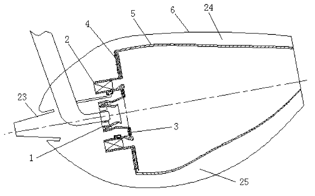
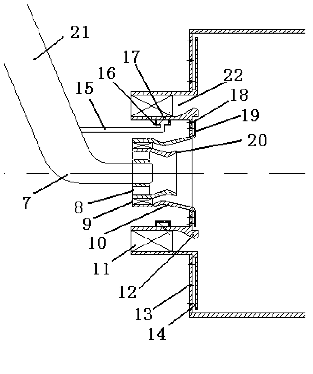
[0028] A lean-fuel premixed pre-evaporation low-pollution combustion chamber with main-stage fuel direct injection in this embodiment is as follows: figure 1 , 2 As shown, it includes the head of the combustion chamber, the flame tube 5, the inner ring passage 25 of the combustion chamber, the outer ring passage 24 of the combustion chamber, the fuel injection rod 21 and the casing, and the fuel injection rod 21 is installed on the casing 6. On the one hand, it is the combustion chamber Oil is supplied to the head, and on the other hand, it bears part of the mechanical force. The head of the combustion chamber is connected to the casing 6 through the fuel injection rod 21, and the head of the combustion chamber, the inner ring channel 25 and the outer ring channel 24 are distributed according to the flow rate Design, the air in the inner and outer ring passages enters the flame tube from the mixing hole and the film cooling hole on the flame tube 5 respectively, and the oil sp...


PUM


Abstract

The invention relates to a lean oil pre-mixing and pre-evaporating low-pollution combustion chamber capable of ejecting main-stage fuel oil directly, and belongs to the field of aero-engines. The core idea of the lean oil pre-mixing and pre-evaporating low-pollution combustion chamber is air classification and fuel oil classification. The lean oil pre-mixing and pre-evaporating low-pollution combustion chamber is composed of an on-duty stage / subsidiary mold and a mainstage / main mold, wherein the on-duty stage is composed of a first-stage axial swirler (8), a second-stage axial swirler (9), a sleeve (10) and an on-duty stage contraction and expansion segment (20), realizes diffusive combustion and provides a stable ignition source; and the main stage comprises a main-stage swirler (11), a main-stage oil supply pipe (15), an oil collection cavity (16), a fuel oil direct-injection type nozzle (17), a main-stage contraction and expansion segment (12) and a main-stage pre-mixing annular cavity (22) and is used for combusting a part of pre-mixed and pre-evaporated lean oil and lowering a high-temperature hotspot so as to reduce the emission of thermal nitric oxide (NOX). The lean oil pre-mixing and pre-evaporating low-pollution combustion chamber is in the mode of lean oil pre-mixing and pre-evaporating combustion with a central classification idea, other properties of the chamber cannot be sacrificed, and the emission of pollutants, including the NOX, smoke, carbon oxide (CO) and unburned hydrocarbon (UHC), of an aero-engine chamber can be effectively lowered at the same time.

Description

technical field [0001] The invention relates to a fuel-lean premixed pre-evaporation low-pollution combustion chamber directly injected by main-stage fuel, and belongs to the technical field of aero-engines. Background technique [0002] At present, civil aviation engines emit more and more pollutants into the atmosphere, and the air pollution is also becoming more and more serious. In order to control the impact of aircraft engine emissions on the environment, the pollution emissions from civil aircraft combustion chambers are required to meet the ICAO CAEP standards. Currently, CAEP6 is implemented, especially for NO X Emissions requirements are getting stricter. In order to meet the CAEP standard, major aero-engine companies and research institutions have carried out research on low-pollution combustion technology. GE has developed the Twin Annular Premixing Swirler (TAPS) combustion technology, which has an emission of about 65% lower; Pratt & Whitney developed the 3rd...

Claims


Application Information

Patent Timeline
IPC IPC(8): F23R3/38F23R3/30
Inventor 颜应文徐榕邓远灏朱嘉伟李诗党龙飞
Owner NANJING UNIV OF AERONAUTICS & ASTRONAUTICS
Learn More