Drive-embedded dynamic folding morphing wing

A variant wing and built-in technology, applied in the field of dynamic models of variant aircraft wind tunnel tests, can solve the problems of key technologies that have not been tackled, and achieve the effect of flexible operation and broad application prospects

Inactive Publication Date: 2013-05-29
中国航空工业空气动力研究院
View PDF6 Cites 11 Cited by
  • Summary
  • Abstract
  • Description
  • Claims
  • Application Information

AI Technical Summary

Problems solved by technology

[0004] At present, Western countries such as Europe and the United States have envisioned the use of piezoelectric technology and local variants of smart materials to realize the folding variants of wings, but these two technologies are still immature and are only in the experimental stage, and the key technologies are still in development. There are many problems that have not been tackled, and there is still a long way to go from practical application

Method used


Image

  • Drive-embedded dynamic folding morphing wing
  • Drive-embedded dynamic folding morphing wing
  • Drive-embedded dynamic folding morphing wing

Examples


Embodiment 1

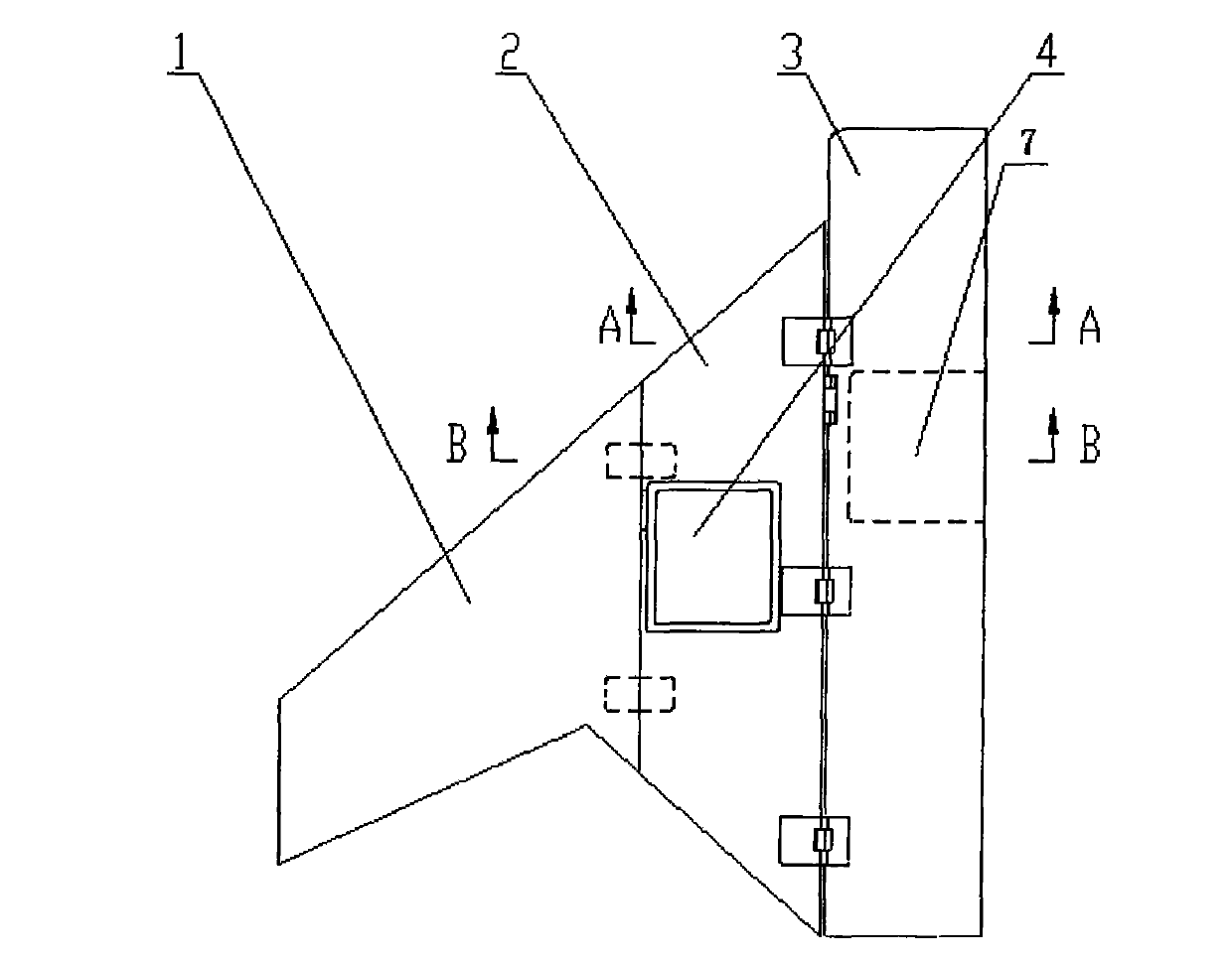
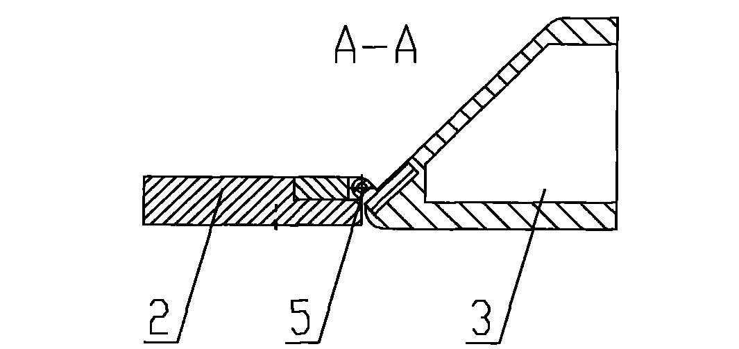
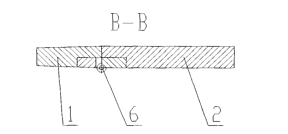
[0014] Such as figure 1 As shown, a drive embedded dynamic folding variant wing includes an outer wing 1, an inner wing 2, an embedded outer wing rotation drive mechanism 4, a fixed rotation shaft 5, a driven rotation shaft 6 and an inner wing rotation drive Mechanism 7, the present embodiment divides the traditional integral wing into two parts, the inner wing 2 and the outer wing 1, which are independent of each other. A driven rotating shaft 6 is provided at the junction of the wings 1, a built-in outer wing rotation drive mechanism 4 is installed on the inner wing 2, a built-in inner wing rotation drive mechanism 7 is installed on the fuselage 3, and a built-in outer wing rotation drive mechanism 7 is installed on the body 3. The wing rotation drive mechanism 4 is completely consistent with the inner wing rotation drive mechanism 7, and all mechanism transmission parts thereof do not protrude from the dynamic model surface.

Embodiment 2

[0016] Under the driving action of the embedded inner wing rotating drive mechanism 7, the inner wing 2 rotates around the fixed rotating shaft 5 at a certain angular velocity; under the driving action of the inner embedded outer wing rotating driving mechanism 4, the outer wing 1 rotates around the driven The rotation axis 6 rotates; during the wing folding process, the rotation directions of the inner wing 2 and the outer wing 1 are opposite, and while folding, it is necessary to keep the chord plane of the outer wing 1 part parallel to the horizontal plane of the fuselage; and, the inner wing 2 and the outer wing 1 are The folding process of the outer wing 1 is controlled by a digital control system, which can stop at a certain folding angle at any time as required, and the folding angular velocity can be controlled within a certain range. The invention has the advantages of flexible operation, stable and no noise, and can well withstand the aerodynamic load on the dynamic m...


PUM


Abstract

The invention relates to a drive-embedded dynamic folding morphing wing. The morphing wing comprises an inner wing, an outer wing, a fixed rotary shaft, a driven rotary shaft, an embedded inner wing rotation drive mechanism and an embedded outer wing rotation drive mechanism. The fixed rotary shaft is arranged at the junction of the inner wing with an airplane body, the driven rotary shaft is arranged at the junction of the inner wing with the outer wing, the embedded outer wing rotation drive mechanism is mounted on the inner wing, and the embedded inner wing rotation drive mechanism is installed on the airplane body. Under the drive of the embedded inner wing rotation drive mechanism, the inner wing rotates around the fixed rotary shaft; and under the drive of the embedded outer wing rotation drive mechanism, the outer wing rotates around the driven rotary shaft, and in a folding process of the morphing wing, the inner wing and the outer wing are opposite in rotary directions, and the wing chord plane of the outer wing is parallel with the airplane body horizontal plane. The drive-embedded dynamic folding morphing wing has the advantages of being flexible in operation, stable and noise-free and capable of bearing the airload imposed on a dynamic model during the wind tunnel test.

Description

technical field [0001] The invention relates to a dynamic model of a variant aircraft wind tunnel test, in particular to a driving embedded dynamic folding variant wing. Background technique [0002] It has always been the dream of aviation science and technology personnel to fly aircraft faster, higher and farther, but none of the aircraft currently in service in the world can achieve all of the above goals. Due to technical limitations, the design of traditional fixed-wing aircraft can only make compromises in different flight mission states. Therefore, the aircraft can only have good aerodynamic performance in a certain airspace range and a certain speed range. When flying away from the design point, the aerodynamic performance drops very sharply, resulting in a single model with single functions and low maneuverability and flexibility. restricted. [0003] Mutant aircraft may be able to overcome the shortcomings of traditional aircraft design. Morphing vehicle technol...

Claims


Application Information

Patent Timeline
Patent Type & Authority Applications(China)
IPC IPC(8): G01M9/06
Inventor 李强刘铁中李周复蒋增由亮李雁鹏
Owner 中国航空工业空气动力研究院
Why Eureka
Try Eureka