Cooking device

The technology of a cooking device and a heating device is applied in the field of kitchen utensils, which can solve the problems of insufficient release of food nutrients, low efficiency, slow heating, etc., and achieve the effects of shortening the stewing time, high efficiency and uniform processing.

Active Publication Date: 2013-06-05
汕头市天际电器实业有限公司
View PDF6 Cites 19 Cited by
  • Summary
  • Abstract
  • Description
  • Claims
  • Application Information

AI Technical Summary

Problems solved by technology

For example, the patent No. CN00219773.1 discloses a stew pot comprising a shell and a ceramic liner, an aluminum liner is fixed inside the shell, the ceramic liner is located in the aluminum liner, and the outer wall of the aluminum liner is fixed with Heating ring; the heating ring includes a C-shaped groove with three mica sheets built in, wherein a resistance heating wire is wound on the middle mica sheet; the outer layer of the three mica sheets, that is, the opening of the C-shaped groove,

Method used


Image

  • Cooking device
  • Cooking device
  • Cooking device

Examples


Embodiment 1

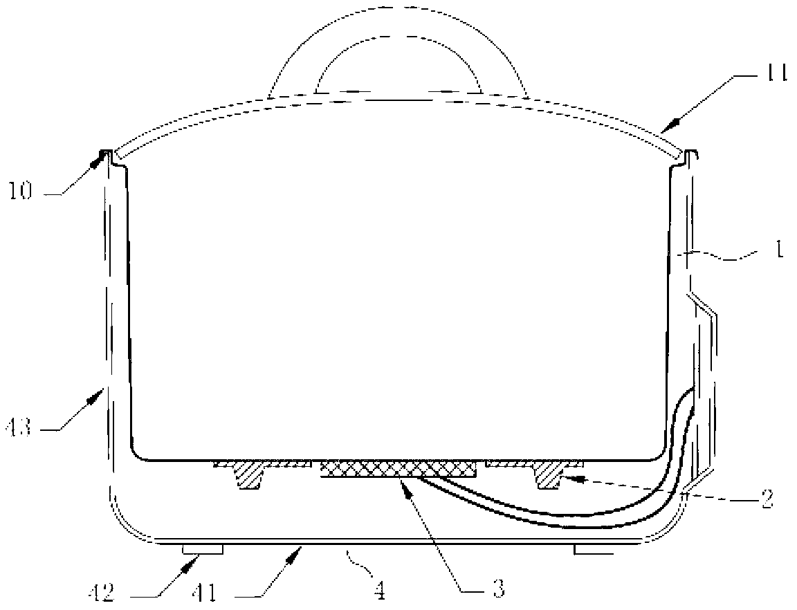
[0024] see figure 1 , the cooking device described in this embodiment includes a container 1 and a cover 11 that is closed with the container 1, and also includes a base 4 for supporting the container 1 and a heating device for heating the container, and the outer bottom surface of the container 1 is An ultrasonic transducer 3 for emitting ultrasonic waves into the container 1 is provided.

[0025] In this embodiment, the above-mentioned container 1 is used to accommodate food materials and soup materials to be processed. The heating device is preferably arranged on the annular heating plate 2 on the outer bottom surface of the container 1. The heating plate 2 and the heating device 3 are located on the same plane. The container 1. The outer edge 10 of the opening is formed at the opening position. The base 4 includes a disc-shaped bottom plate 41 and support feet 42 fixed on the bottom plate 41. A cylindrical outer wall is provided upward along the circumferential direction o...

Embodiment 2

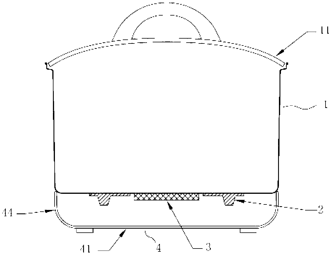
[0029] The difference between this embodiment and Embodiment 1 is that the base 4 in Embodiment 1 is in contact with the outer edge of the opening of the container 1 through the outer wall 43 so as to realize the support of the container 1, while in this embodiment, the base 4 is placed on the outer edge of the container 1. support it at its bottom position. see figure 2 , in this embodiment, the base 4 includes a bottom plate 41 and a base side wall 44 extending upward along the circumference of the bottom plate 41, the base side wall 44 is fixed on the bottom plate 41 and integrally formed with the bottom plate 41, the The base side wall 44 is in contact with the outer bottom surface of the container 1 and supports the container 1 . The side wall 44 of the base is in the shape of a shell to surround the heating plate 2 and the ultrasonic transducer 3 , and the inner container is made of ceramics, aluminum alloy or stainless steel.

[0030] When the cooking device of this ...

Embodiment 3

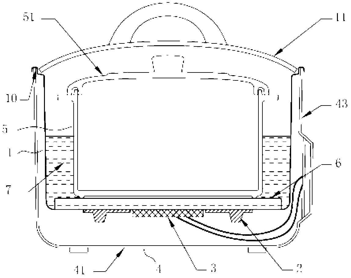
[0032] see image 3 , The difference between this embodiment and Embodiment 1 and Embodiment 2 lies in: the soup and ingredients contained in the container 1 in Embodiment 1 and Embodiment 2, but in this embodiment, the heat transfer liquid 7 contained in the container 1. Specifically, in this embodiment, the container 1 is rolled back at the opening position to form the outer edge 10 of the opening, the base 4 includes a bottom plate 41, and the bottom plate 41 extends upward in the circumferential direction to form an outer side wall 43, and the outer side wall 43 and the container The outer edge 10 of the opening of 1 interferes with and supports the container 1. According to needs, the outer edge 10 of the opening and the outer side wall 43 can be fixedly or flexibly connected. Further, the outer side wall 43 of the container 1 and the base 4 can be integrally formed. . The container 1 is equipped with a heat-conducting liquid 7 , immersed in the heat-conducting liquid 7 ...


PUM


Abstract

The invention relates to a cooking device which comprises a container, a cover covering the container, a base and a heating device. The base is used for supporting the container, and the heating device is used for heating the container. An ultrasonic transducer used for emitting ultrasonic waves into the container during stewing is arranged on the outer bottom surface of the container, so that 'cavitation action' effect on soup is generated by the ultrasonic waves emitted into the container, and nutrient substances of food can be precipitated and dissolved in the soup to the greatest extent so as to convenient for absorption of human bodies. The ultrasonic transducer is arranged on the periphery of the container, so that ultrasonic waves can cover soup in larger area, 'cavitation action' range is larger, and food and soup can be more uniformly processed by the cooking device. The cooking device can greatly shorten food stewing time and has the advantages of high efficiency and low energy consumption.

Description

technical field [0001] The present invention relates to a kitchen appliance, and more particularly, to a cooking device. technical background [0002] Most of the existing cooking utensils that use electricity as energy source achieve the purpose of heating by driving the heating plate to generate heat or electromagnetic heating. Many places can fully release the nutrients of the ingredients. The usual method is to prolong the stewing time for "slow stewing". For example, the patent No. CN00219773.1 discloses a stew pot comprising a shell and a ceramic liner, an aluminum liner is fixed inside the shell, the ceramic liner is located in the aluminum liner, and the outer wall of the aluminum liner is fixed with Heating ring; the heating ring includes a C-shaped groove with three mica sheets built in, wherein a resistance heating wire is wound on the middle mica sheet; a ring of iron sheets is provided on the outer layer of the three mica sheets, that is, at the opening of the ...

Claims


Application Information

Patent Timeline
IPC IPC(8): A47J27/00A47J36/00
Inventor 马少军杨扬
Owner 汕头市天际电器实业有限公司
Why Eureka
Try Eureka