X-ray diagnostic apparatus and X-ray beam limiting control method

A diagnostic device and X-ray technology, applied in the fields of radiological diagnosis instruments, diagnosis, radiation/particle processing, etc., can solve the problems of reduced image quality and increased radiation dose.

Active Publication Date: 2015-03-11
TOSHIBA MEDICAL SYST CORP
View PDF5 Cites 0 Cited by
  • Summary
  • Abstract
  • Description
  • Claims
  • Application Information

AI Technical Summary

Problems solved by technology

However, in the SID-dependent switching method, since it does not depend on the thickness of the subject, if the SID is long, a thin additional filter is used. The problem that the amount of radiation received is increased compared with the thickness switching method
In addition, there is a problem of image quality degradation in the subject thickness switching method and the SID switching method.

Method used


Image

  • X-ray diagnostic apparatus and X-ray beam limiting control method
  • X-ray diagnostic apparatus and X-ray beam limiting control method
  • X-ray diagnostic apparatus and X-ray beam limiting control method

Examples


no. 1 Embodiment approach )

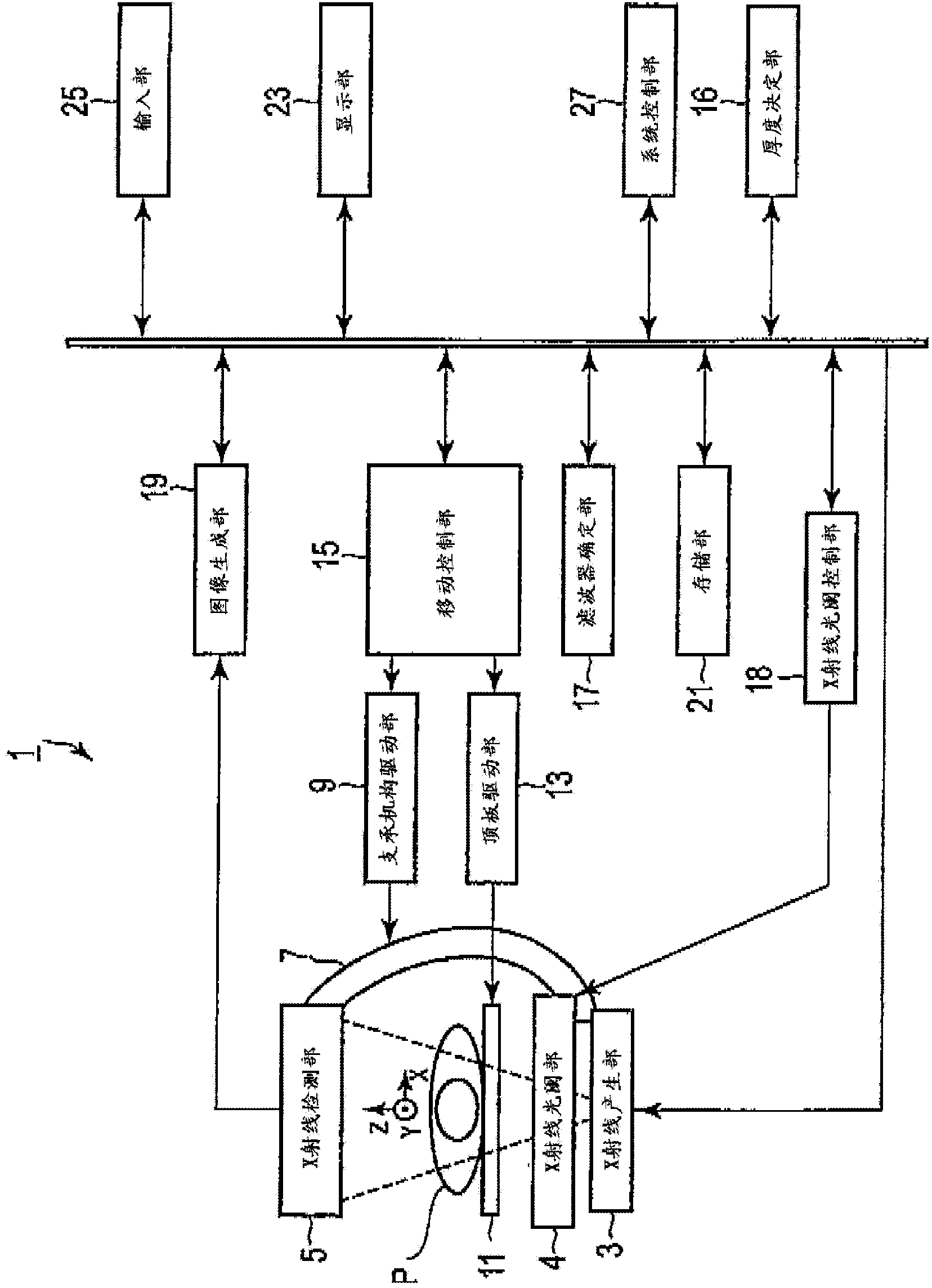
[0024] figure 1 The configuration of the X-ray diagnostic apparatus 1 according to the present embodiment is shown. The X-ray diagnostic apparatus 1 has: an X-ray generation unit 3, an X-ray aperture unit 4, an X-ray detection unit 5, a support mechanism 7, a support mechanism drive unit 9, a top plate 11, a top plate drive unit 13, a movement control unit 15, a thickness Determination unit 16 , filter determination unit 17 , X-ray aperture control unit 18 , image generation unit 19 , storage unit 21 , display unit 23 , input unit 25 , and system control unit 27 .

[0025] The X-ray generator 3 has an X-ray tube and a high voltage generator (not shown). The high voltage generator generates a tube current supplied to the X-ray tube and a tube voltage applied to the X-ray tube. The high voltage generator supplies tube currents suitable for X-ray imaging and X-ray fluoroscopy to the X-ray tube. The high voltage generator applies tube voltages suitable for X-ray imaging and X-r...

no. 2 Embodiment approach )

[0066] In the second embodiment described below, for the same components as those of the first embodiment, in order to avoid repeated descriptions, the same symbols are assigned to the same components and their detailed descriptions are omitted, and only different components will be described. .

[0067] Figure 6 It is a figure which shows the structure of the X-ray diagnostic apparatus concerning 2nd Embodiment.

[0068] The storage unit 21 stores data of a first phantom having the same thickness as the subject. The data of the first phantom is, for example, data having an X-ray attenuation coefficient of water. The storage unit 21 stores data of a second phantom having a predetermined thickness thinner than the subject. The data of the second phantom is data having the X-ray attenuation coefficient of the contrast agent. The predetermined thickness refers to, for example, the diameter of a blood vessel. The storage unit 21 stores a correspondence table of additional fi...


PUM


Abstract

According to one embodiment, an X-ray diagnostic apparatus includes an X-ray generation unit, X-ray detection unit, X-ray beam limiting unit, and X-ray beam limiting control unit. The X-ray generation unit generates X-rays. The X-ray detection unit detects the X-rays generated by the X-ray generation unit and transmitted through an object placed on a tabletop. The X-ray beam limiting unit includes a plurality of filters to harden radiation quality of the generated X-rays. The X-ray beam limiting control unit controls the X-ray beam limiting unit to place a filter between the X-ray generation unit and the object, which filter is specified from the plurality of filters based on the thickness of the object and the distance between the X-ray generation unit and the X-ray detection unit.

Description

[0001] This application claims the priority of Japanese Patent Application No. 2011-264505 filed on December 2, 2011, and uses the entire content of the above-mentioned Japanese Patent Application in this application. technical field [0002] The present invention relates to an X-ray diagnostic device and an X-ray aperture control method. Background technique [0003] Conventionally, an X-ray diagnostic apparatus has an X-ray diaphragm capable of adjusting the X-ray irradiation range. In order to adjust the linear quality of X-rays, the X-ray aperture unit has a plurality of filters (hereinafter referred to as additional filters) having different thicknesses. An additional filter (also referred to as a linear filter or a beam spectral filter) can reduce soft lines of X-rays generated by an X-ray generator in an X-ray diagnostic apparatus. The switching of the plurality of additional filters is performed based on, for example, the thickness of the subject estimated from the ...

Claims


Application Information

Patent Timeline
Patent Type & Authority Patents(China)
IPC IPC(8): A61B6/00
CPCA61B6/588A61B6/544G21K1/10A61B6/583A61B6/4035G01N23/02A61B6/481
Inventor 白石邦夫松本正典大桥俊平
Owner TOSHIBA MEDICAL SYST CORP
Why Eureka
Try Eureka