
Multi-beam frequency compound imaging method and system thereof

A technology of frequency compounding and imaging methods, which is applied in the directions of acoustic wave diagnosis, infrasonic wave diagnosis, ultrasonic/sonic wave/infrasonic wave diagnosis, etc. It can solve problems such as ultrasonic beam distortion, image quality reduction, and receiving beam distortion, so as to increase frame rate and improve resolution rate, to achieve the effect of beam distortion correction

Active Publication Date: 2013-06-05
VINNO TECH (SUZHOU) CO LTD
View PDF7 Cites 5 Cited by
  • Summary
  • Abstract
  • Description
  • Claims
  • Application Information

AI Technical Summary

Problems solved by technology

However, since the transmitting beam has a pulling effect on the receiving beams on both sides, the closer to the focal point, the more obvious the pulling effect and the more serious the distortion of the receiving beam
Therefore, it can be considered that the actual position of the ultrasonic echo receiving beam after the combined effect of emission and reception is in D and E, which deviates from the physical scanning line positions B and C, which causes the distortion of the ultrasonic beam and reduces the image quality

Method used


Image

  • Multi-beam frequency compound imaging method and system thereof
  • Multi-beam frequency compound imaging method and system thereof
  • Multi-beam frequency compound imaging method and system thereof

Examples


Embodiment Construction

[0043] The present invention will be described in detail below in conjunction with specific embodiments shown in the accompanying drawings.

[0044] Please refer to Figure 2 to Figure 5 As shown, it shows an embodiment of the multi-beam frequency compound imaging method of the present invention.

[0045] Such as figure 2 As shown, a beam stacking method in an ultrasonic imaging system includes the following steps:

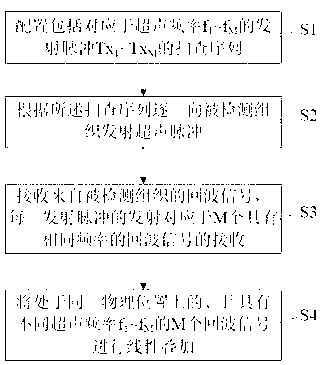
[0046] S1, the configuration includes corresponding to the ultrasonic frequency f 1 ~ f M The transmit pulse Tx 1 ~Tx M The scan sequence; wherein, M is greater than or equal to 2.

[0047] S2. Transmit ultrasonic pulses to the detected tissue one by one according to the scanning sequence;

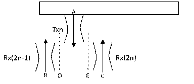
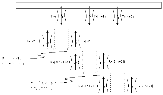
[0048] S3. Receive echo signals from the detected tissue; wherein, the emission of each emission pulse corresponds to the reception of M echo signals with the same frequency, wherein the M echo signals are symmetrical with respect to the corresponding emission pulses ...


PUM


Abstract

The invention provides a multi-beam frequency compound imaging method and a system thereof. The method includes steps of (1) allocating scanning arrays comprising a scanning array which corresponds to transmission pulses Tx1-TxM of ultrasonic frequencies f1-fM, (2) transmitting ultrasonic pulses to detected tissues, (3) receiving echo signals from the detected tissues, wherein the emission of each transmission pulse corresponds to receiving of M echo signals in the same frequency, (4) and carrying out linear superposition on the M echo signals which are arranged on the same physical position and are in different ultrasonic frequencies f1-fM. Though adoption of the multi-beam receiving technology, the purposes of beam distortion correction and ultrasound compound of the multi-frequency signals are achieved at the same time, and the method is simple and easy to realize.

Description

technical field [0001] The invention relates to the technology in the field of ultrasonic diagnosis, in particular to a multi-beam frequency compound imaging method and system. Background technique [0002] Frequency compound imaging technology transmits fundamental wave signals with several frequencies, and collects ultrasonic scan lines with different frequency bandwidths at the same time, and finally forms an ultrasonic image. While ensuring the time resolution, the frequency compound imaging technology further enhances the spatial resolution of the ultrasound image and the uniformity of the overall image. [0003] In the prior art, there are two common frequency compound imaging techniques, one of which is: transmit an ultrasonic wave at a set physical scan line position, the ultrasonic wave has a certain frequency bandwidth, and then receive an ultrasonic echo at the same position Wave signal, and the received same echo signal is demodulated and filtered through differ...

Claims


Application Information

Patent Timeline
IPC IPC(8): A61B8/00
Inventor 陈惠人
Owner VINNO TECH (SUZHOU) CO LTD
Features
  • Generate Ideas
  • Intellectual Property
  • Life Sciences
  • Materials
  • Tech Scout
  • Unparalleled Data Quality
  • Higher Quality Content
  • 60% Fewer Hallucinations
Learn More