Compression roller device provided with buffering mechanisms

A technology of buffer mechanism and pressure roller device, which is applied in the field of pressure roller buffer devices, which can solve the problems that the wear of the buffer material cannot be effectively solved, the frame of the pressure roller is tilted and deformed, and there is no buffer installed, so as to avoid bad roll shape and reduce impact Powerful and easy to replace

Active Publication Date: 2014-12-10
SHANGHAI MEISHAN IRON & STEEL CO LTD
View PDF9 Cites 0 Cited by
  • Summary
  • Abstract
  • Description
  • Claims
  • Application Information

AI Technical Summary

Problems solved by technology

Since the coiler is equipped with coiling aids and other equipment, the distance between the coiler and the strip steel turning roll is long, and the frame for fixing the pressure roll is also very long. The pressure roll is generally made of polyurethane material, but it still has a certain hardness; The frame of the fixed pressure roller is driven by a hydraulic cylinder, but there is no buffer. These two problems lead to an impact force between the pressure roller and the steel coil when the pressure roller is pressed down, and the impact force causes an indentation on the steel coil. Time Over a long period of time, the frame of the pressure roller will be tilted and deformed, so that when the pressure roller is pressed down, it will be pressed on one side of the steel coil first, and then all of it will contact the steel coil, which will easily cause deviation when the end of the strip is coiled, affecting the shape of the coil
[0003] After searching, it was found that the Chinese patent CN200320122626.7 "buffer roller" and the Chinese patent CN96231508.7 "shock-absorbing and noise-reducing composite roller" both use buffer materials to make the roller body, which can reduce the impact of the object on the roller to a certain extent. However, the long-term contact between the roller body and the object, the wear phenomenon of the buffer material cannot be effectively solved
Therefore not suitable for strip coiling

Method used


Image

  • Compression roller device provided with buffering mechanisms
  • Compression roller device provided with buffering mechanisms
  • Compression roller device provided with buffering mechanisms

Examples


Embodiment Construction

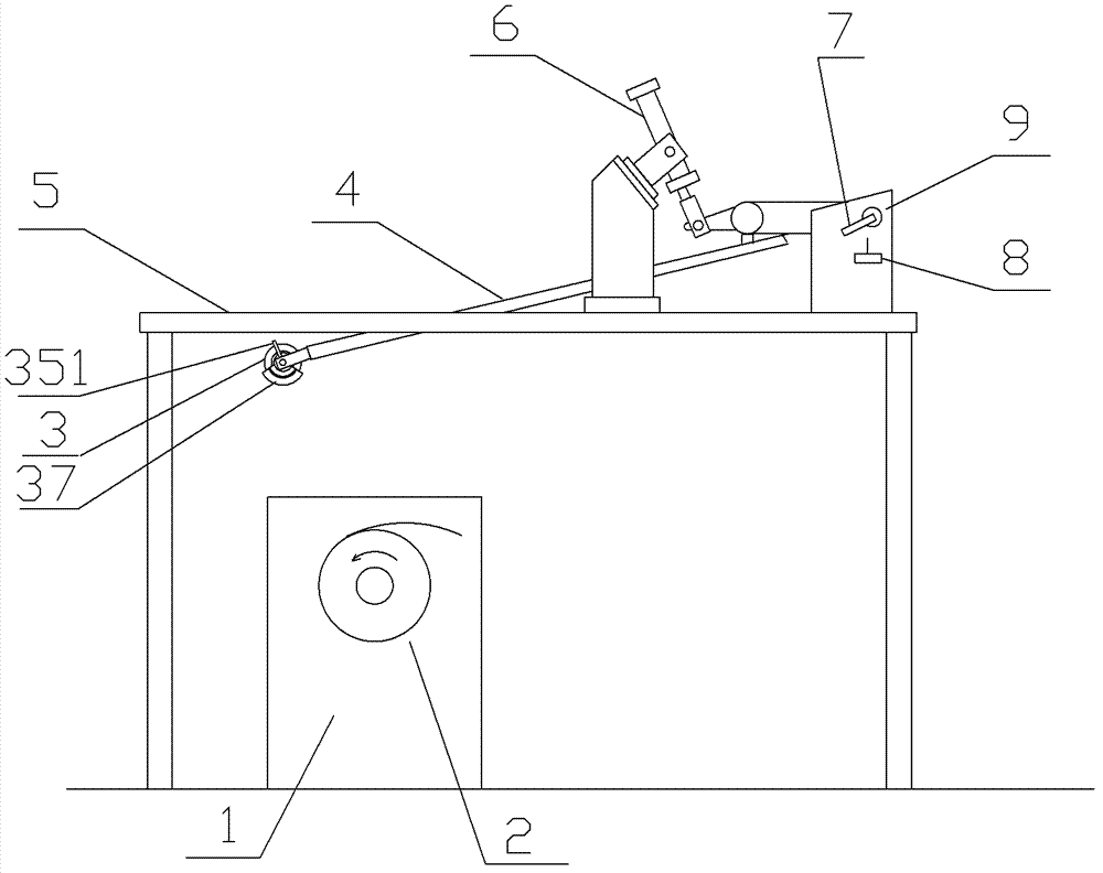
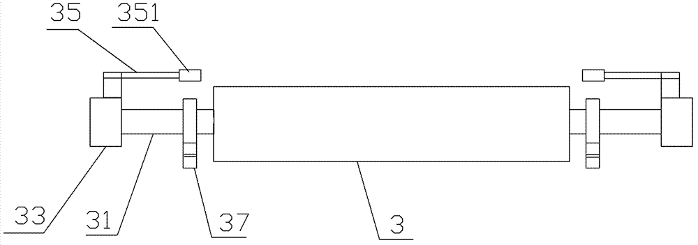
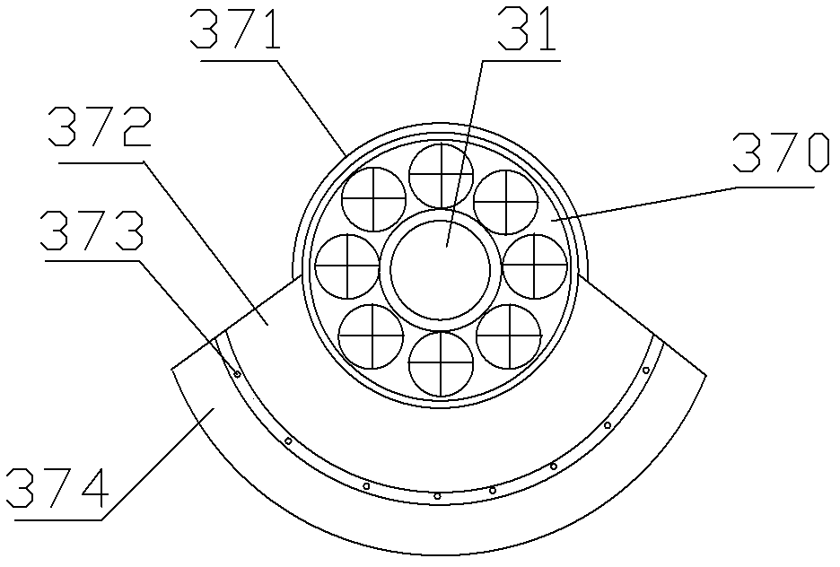
[0017] Such as figure 1 As shown in -4, this embodiment has a pressure roller device with a buffer mechanism, which consists of: a support platform 5, a pressure roller frame seat 9, a pressure roller frame 4, and a pressure roller shaft fixed by the pressure roller bearing seat 33 and the pressure roller frame 4 31. The improvement of the pressure roller 3 installed on the pressure roller shaft 31 is that it also includes a buffer mechanism 37 installed on the pressure roller shaft at both ends of the pressure roller. The buffer mechanism 37 includes: installed on the pressure roller shaft The rolling bearing 370 on 31, the outer circle of the rolling bearing 370 is provided with an elastic buffer body 374, and the elastic buffer body 374 has a cylindrical surface concentric with the pressure roller shaft 31 with an arc of 150° (generally between 90°-180°). The radius of the cylindrical surface is greater than the radius of the pressure roller 3 by 5 cm (generally 3-10 cm), a...


PUM


Abstract

The invention provides a compression roller device provided with buffering mechanisms. The buffering mechanisms of the compression roller device are mounted on the portions, at two ends of a compression roller, of a compression roller shaft. Each buffering mechanism comprises an elastic buffering body which can rotate around the compression roller shaft, a soft magnetic component fixed with the elastic buffering body, and an electromagnet device arranged above the elastic buffering body. When the compression roller is pressed down, the elastic buffering bodies abut against a stationary steel coil in a pressed mode, the compression roller and a compression roller framework are enabled to be buffered, a coiling machine starts to run and drives the steel coil to rotate, while the elastic buffering bodies rotate in the direction opposite to the rotating direction of the steel coil, when the elastic buffering bodies break away from the steel coil, the soft magnetic components are attracted by the electromagnet devices, so that the buffering mechanisms quit working completely, and only the compression roller contacts the steel coil. When the coiling machine finishes coiling a steel strip and stops rotating, the compression roller is lifted up, the electromagnet devices are de-energized, and then the elastic buffering bodies drop naturally and prepare for a next step. The buffering mechanisms of the compression roller device has a quitting function, and therefore the situation that the elastic buffering bodies contact the steel coil for a long time to cause abrasion is effectively avoided.

Description

technical field [0001] The invention relates to a buffer device for a pressure roller, in particular to a pressure roller device with a buffer mechanism which adopts an upper pressing roller mode. Background technique [0002] When the coiler of the export equipment of the cold rolling mill production line is coiling at the end of the steel coil, the upper pressure roller needs to be pressed down to press the tail of the strip to prevent the tail of the strip from being deviated and scattered during coiling, and to ensure that the appearance of the steel coil is neat. Since the coiler is equipped with coiling aids and other equipment, the distance between the coiler and the strip steel turning roll is long, and the frame for fixing the pressure roll is also very long. The pressure roll is generally made of polyurethane material, but it still has a certain hardness; The frame of the fixed pressure roller is driven by a hydraulic cylinder, but there is no buffer. These two pro...

Claims


Application Information

Patent Timeline
Patent Type & Authority Patents(China)
IPC IPC(8): B21C47/26B21C47/02
Inventor 李明王海军
Owner SHANGHAI MEISHAN IRON & STEEL CO LTD
Why Eureka
Try Eureka