Anisotropism sintering rare earth permanent magnetic material radial orientation device and orientation method thereof

A rare-earth permanent magnet and anisotropic technology, which is applied in the direction of magnetic materials, magnetic objects, electrical components, etc., can solve the problems of difficult demolding of molded objects, reduction of molded body density, and influence on the uniform filling of magnetic powder, so as to achieve easy demoulding , Improvement of magnetic properties and improvement of orientation strength

Active Publication Date: 2015-03-04
NINGBO CANMANG TECH
View PDF7 Cites 0 Cited by
  • Summary
  • Abstract
  • Description
  • Claims
  • Application Information

AI Technical Summary

Problems solved by technology

Since magnetic field orientation and compression molding are carried out simultaneously during orientation compression molding of magnetic powder, under pressure, the density of magnetic powder becomes larger and larger, and the activity space of magnetic powder becomes smaller and smaller, which leads to agglomeration and bridging of magnetic powder
On the one hand, the agglomeration and bridging of magnetic powder will affect the uniform filling of magnetic powder and cause large gaps, which will reduce the density of the compacted compact and cannot obtain high magnetic properties. It will also increase accordingly, the residual magnetism is strong, and it is difficult to demould the molded body

Method used


Image

  • Anisotropism sintering rare earth permanent magnetic material radial orientation device and orientation method thereof
  • Anisotropism sintering rare earth permanent magnetic material radial orientation device and orientation method thereof
  • Anisotropism sintering rare earth permanent magnetic material radial orientation device and orientation method thereof

Examples


Embodiment 1

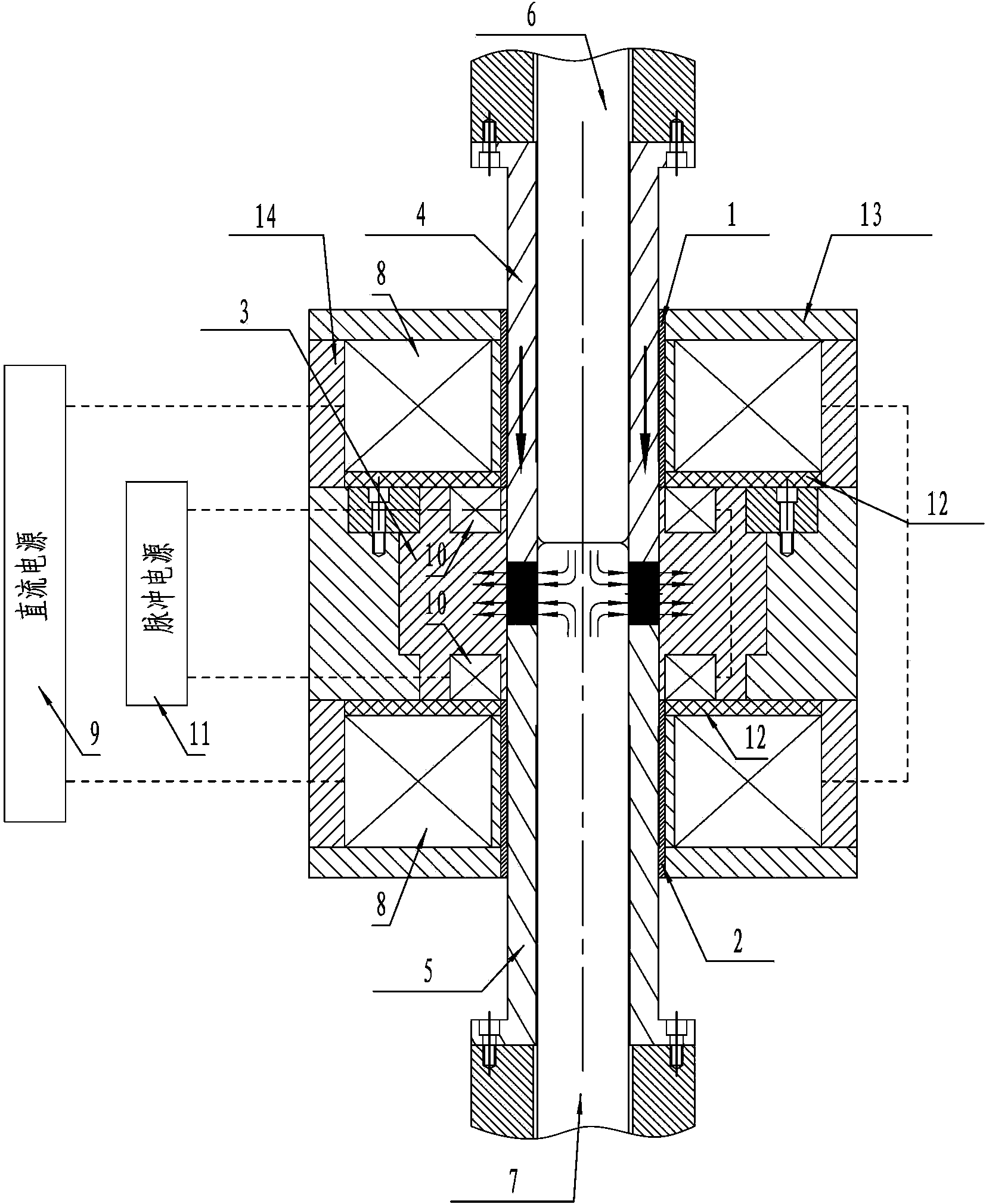
[0028] Embodiment one: if figure 1 As shown, a radial orientation device for anisotropic sintered rare earth permanent magnet materials comprises an upper die case 1, a lower die case 2, a female die 3 placed between the upper die case 1 and the lower die case 2, and an upper The upper punch 4 in the die cover 1, the lower punch 5 placed in the lower die cover 2, the upper mandrel 6 placed in the upper punch 4, the lower mandrel 7 placed in the lower punch 5, A pair of DC coils 8 and a DC power supply 9 connected to the pair of DC coils 8 outside the upper mold cover 1 and the lower mold cover 2 are also provided with a pair of pulse coils 10 and a pulse power supply 11 connected to the pair of pulse coils 10, The pair of pulse coils 10 are respectively arranged on the upper and lower parts of the female mold 3, the DC magnetic field parameter generated by the DC power supply 9 and the pair of DC coils 8 is 5000NI (Ampere-turn), the pulse generated by the pulse power supply 11...

Embodiment 2

[0034] Embodiment 2: This embodiment is basically the same as Embodiment 1, the only difference is that the DC magnetic field parameter produced by the DC power supply 9 and the pair of DC coils 8 is 600000NI (Ampere turn), and the pulse power supply 11 and the pair of pulse coils 10 produce The parameter of the pulse magnetic field is 20000000NI (Ampere-turn), the continuous pulse magnetization frequency of the pulse magnetic field is 10 times / second, and the angle between the central axes of the pair of DC coils 8 and the pair of pulse coils 10 is 10 degrees.

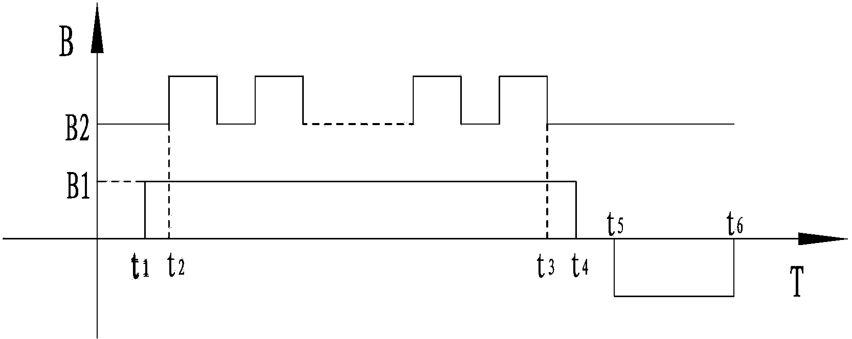
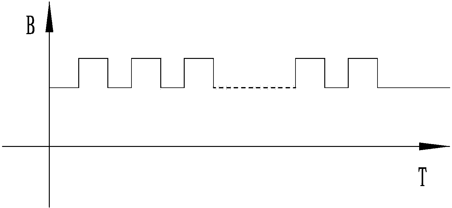
[0035] In the orientation device of the present invention, the DC magnetic field intensity produced by the DC power supply 9 and the pair of DC coils 8 is denoted as B 1 , the pulse magnetic field intensity generated by the pulse power supply 11 and the pair of pulse coils 10 is denoted as B 2 ,Such as figure 2 Shown; The magnetic field strength of the orientation device of the present invention is denoted as B, as ...


PUM


Abstract

The invention provides an anisotropism sintering rare earth permanent magnetic material radial orientation device and an orientation method thereof. The orientation device comprises an upper mold sleeve, a lower mold sleeve, a female mold, an upper punch, a lower punch, an upper core bar, a lower core bar, a pair of direct current coils, a direct current power source, a pair of pulse coils and a pulse power source, wherein the female mold is placed between the upper mold sleeve and the lower mold sleeve, the upper punch is placed inside the upper mold sleeve, the lower punch is placed inside the lower mold sleeve, the upper core bar is placed inside the upper punch, the lower core bar is placed inside the lower punch, the pair of current direct coils are placed outside the upper mold sleeve and the lower mold sleeve, the direct current power source is connected with the pair of direct current coils, and the pulse power source is connected with the pair of pulse coils. The pair of pulse coils are respectively placed on the upper portion and on the lower portion of the female mold, magnetic field parameters produced by the direct current power source and the pair of direct current coils are 5000-600000NI, magnetic field parameters produced by the pulse power source and the pair of pulse coils are 5000-20000000NI, and the continuous pulse magnetizing frequency of a pulsed magnet field is 1-10 times per second. The orientation device and the orientation method thereof have the advantages that orientation is simultaneously conducted through direct current magnetic field and the pulse magnetic field, magnetic performance is improved, residual magnetism on the surface of a magnetic blank after orientation forming is lower than 2 gausses, and mold releasing is easy.

Description

technical field [0001] The invention relates to a radial orientation technology for anisotropic sintered rare earth permanent magnet materials, in particular to a radial orientation device and an orientation method for anisotropic sintered rare earth permanent magnet materials. Background technique [0002] As a high-performance anisotropic permanent magnet, rare earth magnets have excellent magnetic properties and high cost performance, and are widely used in electronics, electric machinery, medical equipment, toys, packaging, hardware machinery, aerospace and other fields. [0003] In the process of preparing sintered permanent magnets, it is usually necessary to put magnetic powder into a magnet forming orienting device, be oriented by a magnetic field, be compressed and molded, and then sintered. At present, the orientation magnetic field in the magnet forming orientation device is generally a DC magnetic field, wherein the DC magnetic field is mainly generated by a clos...

Claims


Application Information

Patent Timeline
Patent Type & Authority Patents(China)
IPC IPC(8): B22F3/16H01F1/053
Inventor 黄可可
Owner NINGBO CANMANG TECH
Why Eureka
Try Eureka