Device and method for magnetic control of wet process underwater welding
A technology of underwater welding and magnetic control device, which is applied in welding equipment, arc welding equipment, manufacturing tools, etc., can solve the problem that the droplet transfer is not easy to transfer to the base metal, etc., so as to improve welding efficiency, improve performance and technical application. Wide range of effects
- Summary
- Abstract
- Description
- Claims
- Application Information
AI Technical Summary
Problems solved by technology
Method used
Image

Examples
specific Embodiment approach 1
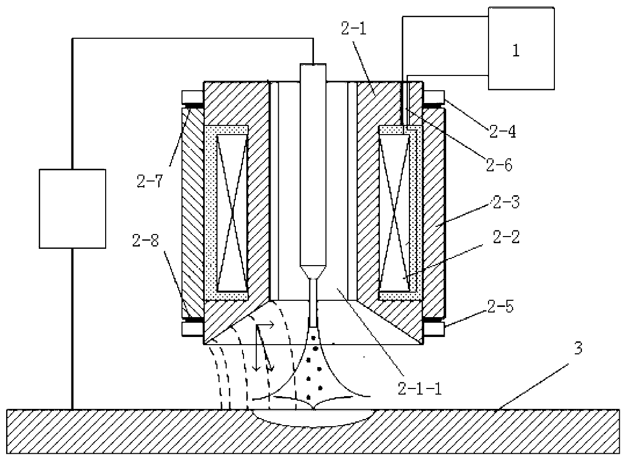
[0025] Specific Embodiment 1: A magnetic control device for wet underwater welding according to this embodiment, which consists of an excitation power source 1, a magnetic core 2-1, an excitation coil 2-2, a copper sleeve 2-3, an upper end The cover 2-4 and the lower end cover 2-5 are composed, the magnetic conducting core 2-1 is hollow cylindrical, the excitation coil 2-2 is wound on the outer surface of the magnetic conducting core 2-1, and the copper sleeve 2-3 Covered outside the excitation coil 2-2, the upper end cover 2-4 is covered on the upper end of the copper sleeve 2-3, and the lower end cover 2-5 is covered on the lower end of the copper sleeve 2-3, which is characterized in that the In the magnetron device for wet underwater welding, the lower end of the permeable core 2-1 flares downward to form an inner conical surface, and the lead-out wire of the excitation coil 2-2 is drawn out through the bakelite ring 2-6, and the The bakelite ring 2-6 is sealed with silica...
specific Embodiment approach 2
[0035] Specific embodiment two: a kind of magnetic control method for wet underwater welding of this embodiment is realized according to the following steps:
[0036] Step 1. Under the condition of water depth of 1-500m, install the magnetic control device above the welding workpiece 3 and connect the excitation power supply 1;
[0037] Step 2, the welding wire is passed through the through hole 2-1-1 of the conductive core 2-1, the shielding gas is applied and the arc between the welding wire and the welding workpiece is ignited to start welding; wherein, the excitation current of the magnetic control device is 1-20A, the excitation frequency is 1-50HZ, the wet underwater welding current is 150-500A, the wire feeding speed is 2-50m / min, the wire diameter is 0.8-2.4mm, and the shielding gas flow rate is 0-50L / min min, the welding voltage is 20-60V, and the welding speed is 500-1000mm / min.
[0038] There are several ways to change the external magnetic field in this embodiment...
specific Embodiment approach 3
[0052] Embodiment 3: This embodiment is different from Embodiment 2 in that: the welding method described in step 2 is FCAW. Other steps and parameters are the same as in the second embodiment.
[0053] Verify beneficial effect of the present invention by following test:
PUM
 Abstract
Description
Claims
Application Information
 - R&D
- Intellectual Property
- Life Sciences
- Materials
- Tech Scout
- Unparalleled Data Quality
- Higher Quality Content
- 60% Fewer Hallucinations
Browse by: Latest US Patents, China's latest patents, Technical Efficacy Thesaurus, Application Domain, Technology Topic, Popular Technical Reports.
© 2025 PatSnap. All rights reserved.Legal|Privacy policy|Modern Slavery Act Transparency Statement|Sitemap|About US| Contact US: help@patsnap.com