Plastic bottle cap capping machine

A technology of capping machine and bottle caps, which is applied in the direction of flanged bottle caps, etc., can solve the problems of complex structure, short service life, and low reliability of performance, and achieve the effects of simple installation and operation, long service life and high reliability

Active Publication Date: 2015-04-01
湖南博雅智能设备有限公司
View PDF11 Cites 1 Cited by
  • Summary
  • Abstract
  • Description
  • Claims
  • Application Information

AI Technical Summary

Problems solved by technology

However, the disadvantages of this capping method are: 1) It is more difficult to manufacture the parts of the machine, and the manufacturing cost is increased, especially the cam that controls the lifting of the capping head is difficult to process, and the heat treatment process is complicated, which is very easy to cause workpieces Unqualified; 2) It is inconvenient to adjust the strength of the gland
The strength of the mechanical gland is also controlled by adjusting the length of the compression spring, that is, adjusting the height of the gland head. After a long time of work, the compression spring may cause fatigue failure, resulting in an unsatisfactory effect of the gland; 3) There are many wearing parts , the cost of accessories increases
[0006] To sum up, the existing plastic bottle cap capping machine has a complex structure, difficult processing, inconvenient force adjustment, low performance reliability, short service life and high cost.

Method used


Image

  • Plastic bottle cap capping machine
  • Plastic bottle cap capping machine
  • Plastic bottle cap capping machine

Examples


Embodiment Construction

[0030] Preferred embodiments of the present invention will be described in detail below in conjunction with the accompanying drawings.

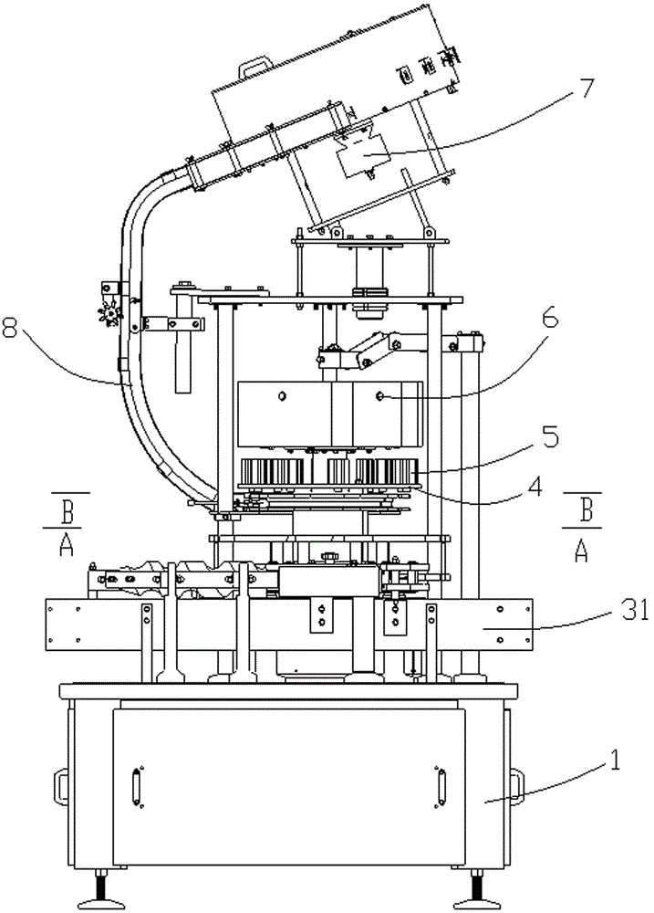
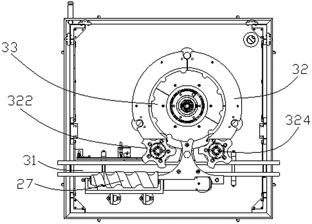
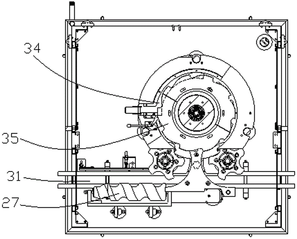
[0031] see Figure 1 to Figure 3 , the plastic bottle cap capping machine of the present invention comprises a frame 1, a drive assembly 2 located at the bottom of the frame 1 (see Figure 4 ) and a bottle cap positioning assembly set on the frame 1 and driven by the drive assembly 2, the bottle cap positioning assembly includes a conveyor belt 31 set on the frame 1 for conveying bottles, a set On one side of the conveyor belt 31, a bottle supporting rotary plate 32 for positioning the bottle body, a central positioning plate 33, a bottle cap tray 34 and a cap shifting plate set coaxially and sequentially on the bottle supporting rotary plate 32 35. The capping disc 35 is provided with a capping rotary disc 4, and the capping rotary disc 4 is provided with a plurality of capping head devices 5 for pressing bottle caps. A central control box...


PUM


Abstract

The invention provides a plastic bottle cap capping machine comprising a rack, a driving component and a bottle cap positioning component. The driving component is arranged at the bottom of the rack. The bottle cap positioning component is arranged on a base support, driven by the driving component, and comprises a conveying belt, a bottle support revolving disc, a central positioning disc, a bottle cap tray and a bottle cap shifting disc, wherein the conveying belt is used for conveying bottles, the bottle support revolving disc is used for positioning the bottles, and the central positioning disc, the bottle cap tray and the bottle cap shifting disc are coaxially sequentially sleeved on the bottle support revolving disc. A bottle cap pressing revolving disc is arranged on the bottle cap shifting disc, a plurality of bottle cap pressing devices used for pressing bottle caps are arranged on the bottle cap pressing revolving disc, and a singlechip controller and an electromagnetic valve set are arranged above the bottle cap pressing revolving disc. A bottle cap arranging machine mounted with bottle caps is arranged on the top portion of the rack and connected to the bottle cap tray via a sliding cover groove. The plastic bottle cap capping machine is simple to mount and operate, high in reliability, convenient for force adjustment, long in service life and low in cost.

Description

technical field [0001] The invention relates to the technical field of bottled beverages, in particular to a plastic bottle cap capping machine. Background technique [0002] With the improvement of anti-theft performance requirements for bottle caps in liquor packaging, three-proof caps and four-proof caps are gradually replacing the original anti-theft caps and crown caps. The plastic anti-theft caps represented by the soft and peaceful series of the seed winery are widely used. The winery generally adopts the following methods to deal with the pressing problem of this kind of bottle caps. [0003] 1. Manual knocking method: The manual knocking method is to use a wooden hammer to press the bottle cap into the mouth of the wine bottle. The advantage of this method is that it is simple and easy to operate, the investment in equipment is very low, and the quality requirements of operators are not high. However, the disadvantages of this method are also very obvious. In ter...

Claims


Application Information

Patent Timeline
Patent Type & Authority Patents(China)
IPC IPC(8): B67B3/02B67B3/06
Inventor 潘昊刘守先
Owner 湖南博雅智能设备有限公司
Why Eureka
Try Eureka