
Method and apparatus for amplitude adjustment of a stamping bar of a road finisher

A technology for tamping beams and repairing machines, which is used in road repair, roads, roads, etc., can solve problems such as adverse effects on the quality of the material layer to be paved, and achieve the effect of reducing wear and working noise.

Inactive Publication Date: 2013-06-05
BOMAG
View PDF8 Cites 9 Cited by
  • Summary
  • Abstract
  • Description
  • Claims
  • Application Information

AI Technical Summary

Problems solved by technology

This means that the operation of the road finishing machine has to be interrupted, which has a negative impact on the quality of the layer of material to be paved

Method used


Image

  • Method and apparatus for amplitude adjustment of a stamping bar of a road finisher
  • Method and apparatus for amplitude adjustment of a stamping bar of a road finisher
  • Method and apparatus for amplitude adjustment of a stamping bar of a road finisher

Examples


Embodiment Construction

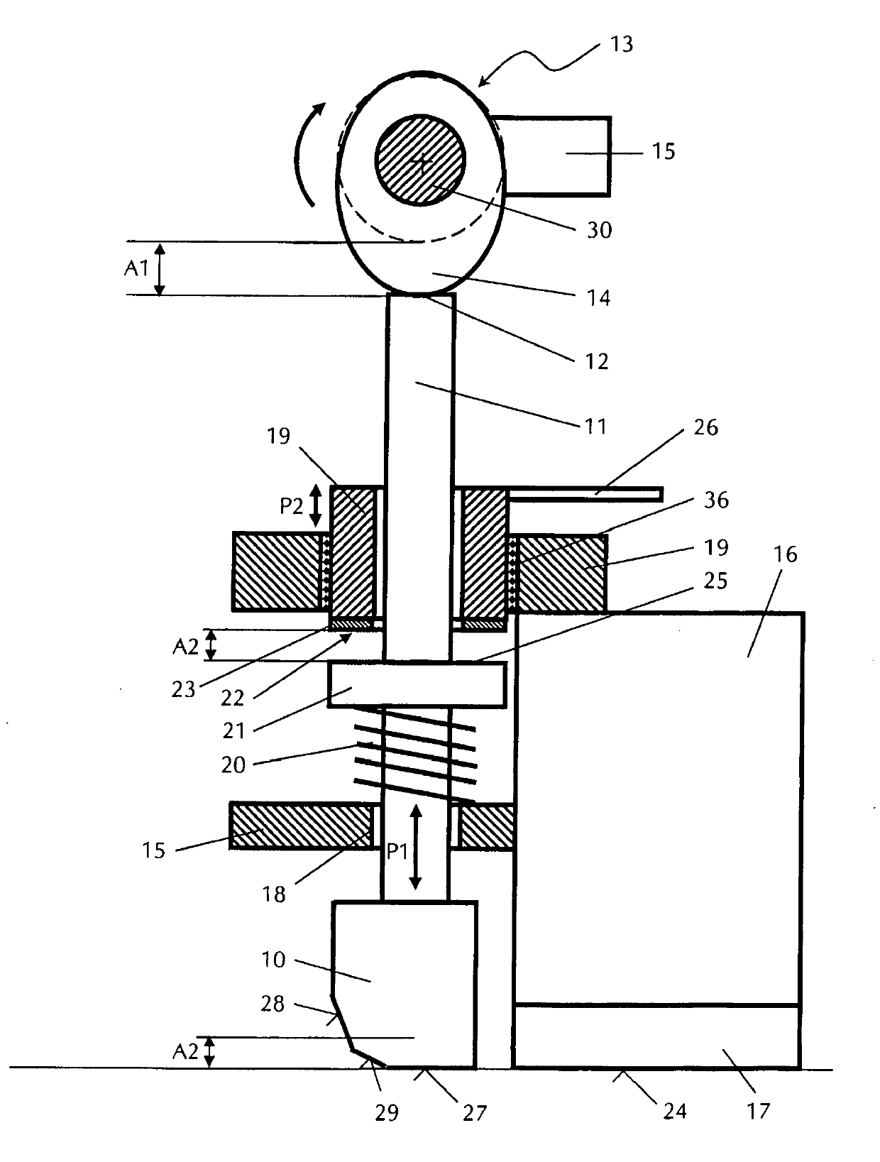
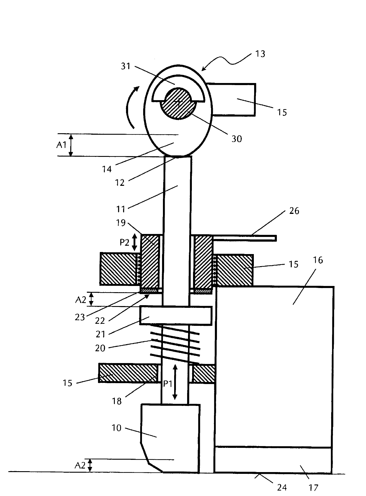
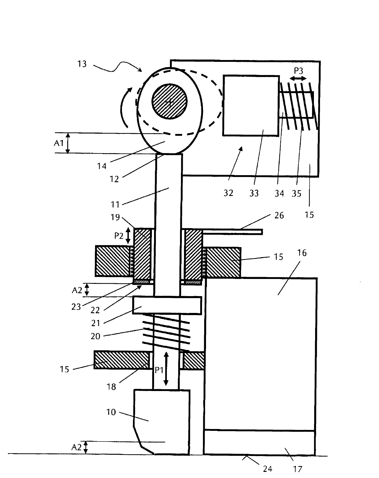
[0036] exist figure 1 , 2 In and 3, reference numeral 10 denotes a tamping beam of a road finisher (not shown), which is installed to be vertically movable so as to perform an oscillating vertical vibration having an upper dead center and a lower dead center. The tamping beam 10 has a vertical push rod 11 with its head side 12 at its upper end. The push rod 11 is moved in one direction by a first drive unit and in the opposite direction by a second drive unit, which is not coupled to the first drive unit. In the example shown, the first drive unit is a cam drive mechanism 13 located at the upper end, and the tamping beam 10 is operatively connected to the cam drive mechanism 13 so that the eccentric cam 14 provided on the shaft 30 can slide on the head. Roll on side 12. Because the cam 14 is not rigidly or positively connected to the tamping beam 10, the cam 14 only moves towards the tamping beam 10 (in the example shown, clockwise when moving towards the tamping beam 10). ...


PUM


Abstract

A method and an apparatus for amplitude adjustment of a stamping bar of a road finisher are disclosed. The stamping bar is configured to perform oscillating vertical vibrations with upper and lower dead center by drive elements, where the upper dead center is shifted and a lower dead center is kept constant. The drive elements, work in a direction on the lower dead center, are decoupled from the drive elements, work in a direction on the upper dead center. The upper dead center is adjusted and the lower dead center is kept constant for adjusting the amplitude. Independent claims are included for the following: (1) a device for amplitude adjustment of a stamping bar of a road finisher; and (2) a stamping bar of a road finisher.

Description

technical field [0001] The present invention relates to a method and apparatus for adjusting the amplitude of a tamping beam of a road finishing machine, having a rotary drive mechanism for the tamping beam, the tamping beam being set to carry out tamping with upper dead center and lower dead center Vertical vibration. Background technique [0002] As is well known, road finishing machines are used to form road surfaces on flat surfaces. In this case, the paving material, such as asphalt, is distributed over the desired pavement width before the paving screed is used, and then the paving screed is used to remove the paving material to achieve the desired thickness of the paving material and smooth the road surface . A tamping beam (also known as a tamper) can be positioned in front of the paving screed, and the tamping beam compacts the paving material through a vertical tamping motion and stabilizes the flow of the material to be paved beneath the paving screed. For this...

Claims


Application Information

Patent Timeline
IPC IPC(8): E01C19/48
CPCE01C19/407E01C19/4833E01C19/486
Inventor K-H·默茨J·瓦格纳
Owner BOMAG
Learn More