Self-suction centrifugal pump

A self-priming centrifugal pump and pump body technology, applied in the field of water pumps, can solve problems such as limited use, and achieve the effects of large water supply, convenient operation, and stable operation

Inactive Publication Date: 2015-05-06
孙九江
View PDF12 Cites 0 Cited by
  • Summary
  • Abstract
  • Description
  • Claims
  • Application Information

AI Technical Summary

Problems solved by technology

Centrifugal pumps also have certain shortcomings, that is, they need to add an appropriate amount of priming fluid to the pump body before starting, and when the suction pipeline is long, it is even necessary to fill the entire pipeline with priming fluid, which limits its use.

Method used


Image

  • Self-suction centrifugal pump
  • Self-suction centrifugal pump
  • Self-suction centrifugal pump

Examples


Embodiment Construction

[0021] In order to further understand the content of the invention, characteristics and effects of the present invention, the following examples are described in detail as follows:

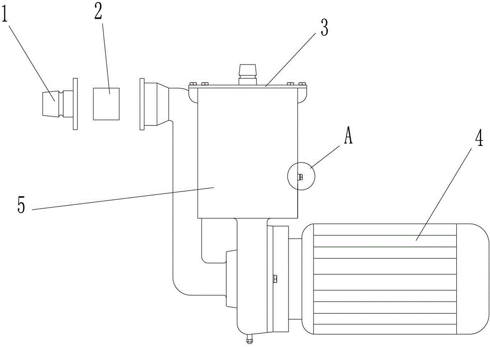
[0022] See figure 1 , the present invention comprises a pump body 5 and a motor 4, and an impeller is installed on the motor shaft of the motor 4.

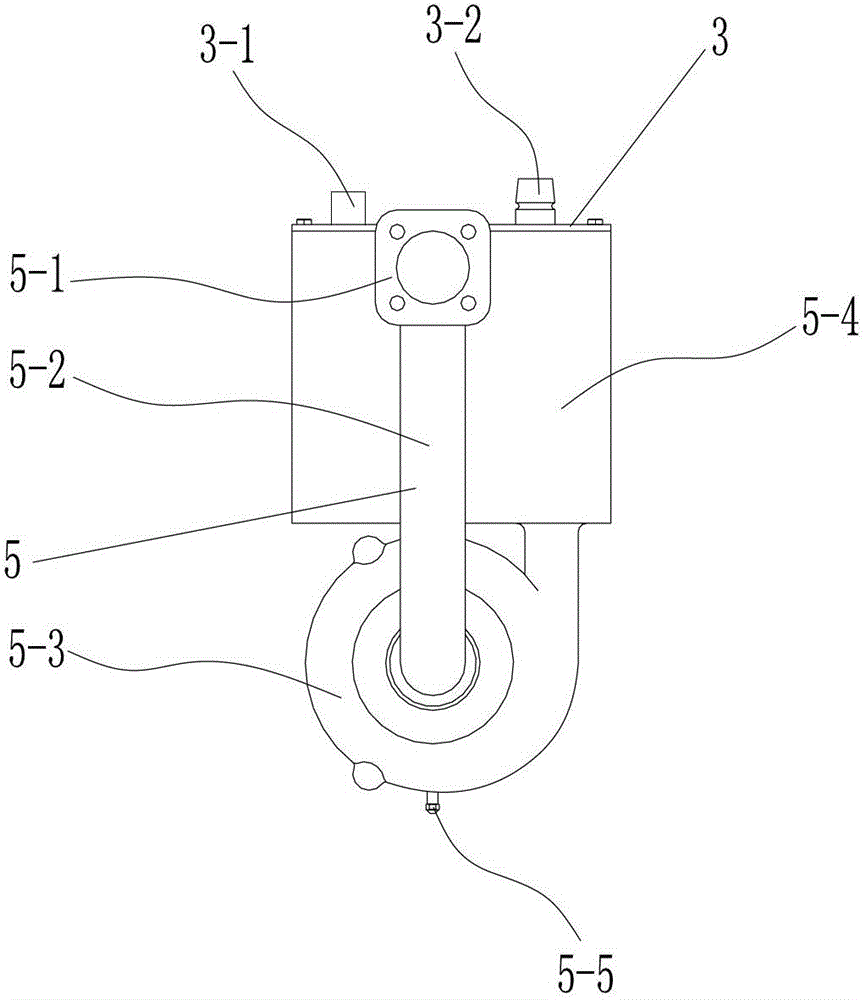
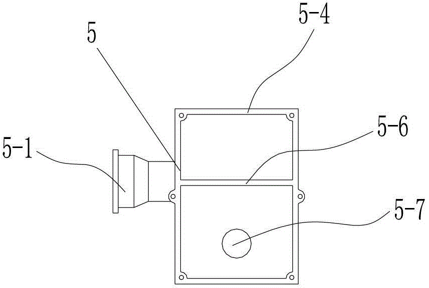
[0023] figure 2 and image 3 The specific structure of the pump body 5 is shown. The pump body 5 includes a water inlet channel 5-2, a volute 5-3 and a water tank 5-4, wherein the volute 5-3 is fastened to the motor disc of the motor 4, and the impeller is located inside the volute 5-3 to provide centrifugal force. In order to improve the overall compactness and firmness of the pump body 5, the water inlet channel 5-2, the volute 5-3 and the water tank 5-4 are integrally cast and formed.

[0024] Water tank 5-4 is rectangular body shape. The volute 5-3 is positioned directly below the water tank 5-4, and its outlet is connected with the upper no...


PUM


Abstract

The invention relates to a self-suction centrifugal pump which comprises a pump body and a motor, wherein impellers are installed on a motor shaft of the motor, the pump body comprises a water inlet channel, a volute and a water tank, the volute is connected to the motor in a buckled mode, and the impellers are located inside the volute. The volute is located under the water tank, and an outlet of the volute is connected with an upper water port arranged in the bottom of the water tank. The bottom end of the water inlet channel is connected with an inlet located in the center of the volute, the outer wall of the upper end of the water inlet channel is attached to the outer wall of the water tank and is provided with a water hole enabling an inner cavity of the water inlet channel and an inner cavity of the water tank to be communicated, and a water supply connector is arranged at the top end of the water inlet channel. The self-suction centrifugal pump further comprises a tank cover arranged on the top of the water tank in a buckled mode, and the tank cover is provided with a water supply port and a water outlet connector. A partition plate parallel with the motor shaft in direction is arranged on the top of the inner cavity of the water tank. The self-suction centrifugal pump further comprises a rotating plate, a plate body at the upper end of the rotating plate rotates with a central line, of a connection portion located at the lower end of the rotating plate, as an axis, a water hole stop block is further arranged on the connection portion through a support rod, and the water hole stop block seals up the water hole when the plate body of the rotating plate rotates to a position where the rotating plate is attached to the partition plate.

Description

technical field [0001] The invention belongs to the technical field of water pumps, in particular to a self-priming centrifugal pump. Background technique [0002] Among the various types of water pumps, the centrifugal pump is a relatively common one. It has been more and more widely used due to its advantages of simple and compact structure, convenient maintenance, high-speed and stable operation. Centrifugal pumps are generally driven by a motor. When the impeller rotates at high speed, the impeller drives the liquid to rotate together. Due to the centrifugal force, the liquid is thrown from the center of the impeller to the outer edge of the impeller, and the kinetic energy increases accordingly. When the liquid enters the pump casing, due to the gradual expansion of the flow channel in the volute-shaped pump casing, the flow rate of the liquid decreases gradually, and part of the kinetic energy is converted into static pressure energy, so the liquid flows out along the ...

Claims


Application Information

Patent Timeline
Patent Type & Authority Patents(China)
IPC IPC(8): F04D9/02F04D13/06F04D29/00
Inventor 孙九江
Owner 孙九江
Why Eureka
Try Eureka