Infrared camera

An infrared and camera technology, applied to cameras, camera bodies, TVs, etc., can solve problems such as messy signals, image resolution effects, highlighting fixed graphics, etc., achieve good shooting, suppress temperature changes, and reduce the impact of temperature changes Effect

Inactive Publication Date: 2013-06-05
TAMRON
View PDF5 Cites 9 Cited by
  • Summary
  • Abstract
  • Description
  • Claims
  • Application Information

AI Technical Summary

Problems solved by technology

[0007] Furthermore, in conventional shading compensation using a shutter, the temperature of the shutter itself affects the resolution of the image, making it difficult to obtain a good image.
In particular, when the shutter is installed near the infrared imaging element, the shutter is easily affected by the heat generated by the infrared imaging element, which is inconvenient in that a fixed pattern noise signal is highlighted in the image.

Method used


Image

  • Infrared camera
  • Infrared camera
  • Infrared camera

Examples


no. 1 approach

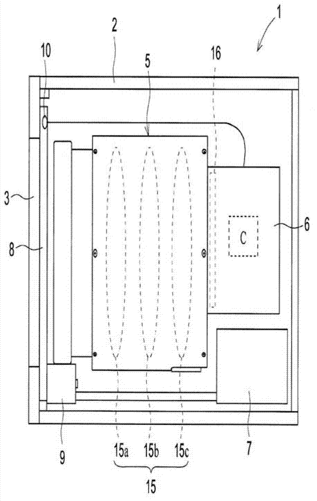
[0026] Structure of the infrared camera: First, regarding the structure of the infrared camera of the first embodiment, use figure 1 Be explained. figure 1 It is a diagram schematically showing the internal structure of the infrared camera according to the first embodiment of the present invention. Such as figure 1 As shown, the infrared camera 1 of the present invention is configured by arranging an infrared lens unit 5 , a camera body 6 , a power supply board (power supply) 7 and the like in a housing 2 of the infrared camera 1 .

[0027] Housing 2 forms the outer contour of infrared camera 1 . The casing 2 has a substantially cylindrical shape. Furthermore, the inside of the casing 2 is constituted as a closed space. Further, on the subject side of the casing 2 , a window portion 3 is formed at a portion of the infrared lens unit 5 facing the subject side of the infrared lens group 15 .

[0028] The window portion 3 is made of a material that transmits infrared rays. ...

no. 2 approach

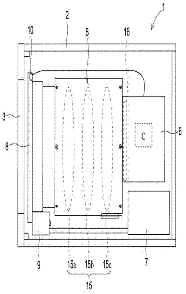
[0052] figure 2 It is a figure which schematically shows the infrared camera of 2nd Embodiment. In the infrared camera 1 according to the second embodiment, the shutter 8 is provided on the side closest to the subject of the infrared lens group 15 . In the infrared camera 1 of this embodiment, as figure 2 As shown, the shutter 8 is located on the subject side of the infrared lens 15a of the infrared lens group 15, and is provided at a position closest to the infrared lens 15a.

[0053] in addition, figure 2 Compared with the infrared camera 1 of the first embodiment described above, only the position of the shutter 8 is different, and other configurations and operations are the same as those described above. Therefore, descriptions of the same configurations and operations are omitted.

[0054] figure 2 The shown shutter 8 may be mounted on the infrared lens unit 5 in addition to being mounted on the inner wall of the casing 2 as in the infrared camera 1 of the first ...

no. 3 approach

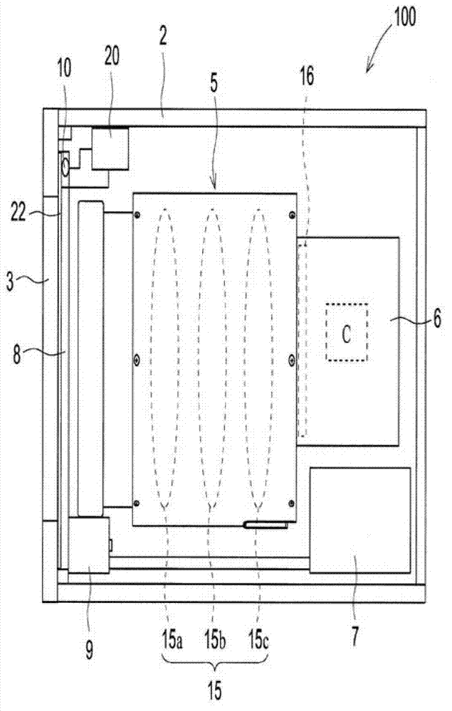
[0057] Next, for the infrared camera of the third embodiment, refer to image 3 Be explained. In addition, in image 3 Among them, the parts given the same reference numerals as those of the infrared camera 1 according to the first embodiment achieve the same or similar effect or function, and therefore description thereof will be omitted here.

[0058] Configuration of Infrared Camera: First, the configuration of the infrared camera according to the third embodiment will be described. Such as image 3 As shown, the infrared camera 100 of the present invention is an infrared camera configured by housing an infrared lens unit 5 , a camera body 6 , a power supply board 7 , etc. in a housing 2 of the infrared camera 100 . The inside of the casing 2 constituting the outer contour of the infrared camera 100 is formed as a closed space.

[0059] The camera body 6 has a control device C that controls the infrared camera 100 . The control device C has a function of compensating and...


PUM


Abstract

An object of the present invention is to provide an infrared camera capable of shading correction with ease and an improved degree of accuracy and has good maintenance ability. To achieve the object, an infrared camera provided with an infrared lens group and an infrared image sensor located at an image focusing surface of the infrared lens group in a housing in which a window is formed at a portion facing the object side of the infrared lens group comprising: a controller correcting a captured image according to an output from the infrared image sensor and outputting the corrected image; a shutter arranged on an infrared light path in the housing from the window to the infrared lens group; and a temperature sensor detecting the temperature of the shutter is adopted.

Description

technical field [0001] The present invention relates to an infrared camera capable of proper shading compensation. Background technique [0002] The infrared camera makes the infrared rays radiated from the subject pass through the infrared lens made of infrared transmissive optical material to form an image on the imaging element located on the imaging surface of the infrared lens, and output it as a thermal image. In recent years, human body detection using this infrared camera has been increasingly used in various fields such as security and automobiles. [0003] In addition to the infrared rays radiated from the subject, the infrared rays radiated from the constituent parts of the infrared camera and the like also enter such an infrared camera at the same time. Infrared rays radiated from components of the infrared camera, etc., adversely affect imaging of infrared rays radiated from a subject. Therefore, compensation for eliminating infrared rays radiated from other t...

Claims


Application Information

Patent Timeline
Patent Type & Authority Applications(China)
IPC IPC(8): G01J5/02G01J5/06H04N5/238G03B17/12
CPCH04N5/33
Inventor 松本健宏
Owner TAMRON
Why Eureka
Try Eureka