Periodic gating unit for suction of worms and air and for granary sampling analysis
A sampling analysis and gating device technology, applied in the sampling device and other directions, can solve the problems of affecting the accuracy of gas sampling results, low insect extraction and extraction efficiency, and low air tightness, etc., and achieves simple structure, reasonable design, and improved The effect of air tightness
- Summary
- Abstract
- Description
- Claims
- Application Information
AI Technical Summary
Problems solved by technology
Method used
Image
Examples
Embodiment 1
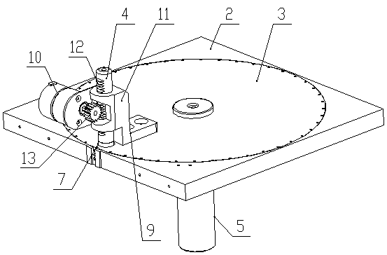
[0018] Embodiment one: if figure 1 with Figure 5 As shown, the granary sampling analysis of the present invention uses a periodic gating device for pumping insects and pumping gas, including a fixed plate 2 with a groove 1 on the surface, a moving plate 3 arranged in the groove 1, and a conduit 4 perpendicular to the moving plate 3 The center of the moving disk 3 is connected with a moving disk motor 5 for driving the moving disk 3 to rotate in the groove 1. The fixed disk 2 is provided with a circle of air guide holes 6 that are evenly arranged around the center of the moving disk 3. The moving disk 3 is provided with There is a through hole 7. When the moving disc rotates, the through hole 7 can communicate with each air guide hole 6 one by one. When designing, the horizontal distance from the center of the through hole 7 to the center of the moving disc 3 is the same as that between the center of each air guide hole 6 and the moving disc. The horizontal distances between ...
Embodiment 2
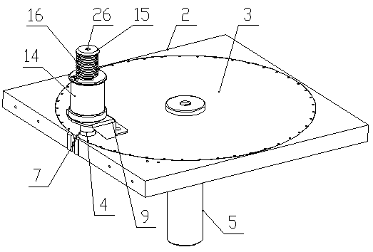
[0021] Embodiment two: if figure 2 with Figure 5 As shown, the difference with Embodiment 1 is that the power drive mechanism includes a bracket 9 arranged on the moving disk 3 and an electromagnet 14 arranged on the bracket 9, the conduit 4 is passed through the electromagnet 14, and the upper part of the conduit 4 is made of iron. Made of magnetic material, the upper end of the conduit 4 is provided with a limit block 15, the limit block 15 and the conduit 4 are integrally formed, the air extraction hole 26 is set at the center of the top of the limit block 15, and the conduit 4 is provided with an electromagnet 14 and a limit block Return spring 16 between 15.
[0022] When in use, the movable disk motor 5 drives the movable disk 3 to rotate at a certain angle, an air guide hole 6 just corresponds to the through hole 7 up and down, the electromagnet 14 is energized, and the magnetic attraction force of the electromagnet 14 to the upper limit block 15 of the conduit 4 is ...
Embodiment 3
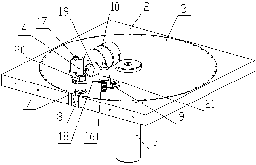
[0023] Embodiment three: as image 3 with Figure 5 As shown, the difference from Embodiment 1 is that the power drive mechanism includes a bracket 9 arranged on the moving disk 3, a stepping motor or a servo motor 10 arranged on the bracket 9, and two vertically arranged on the moving disk 3. A guide post 17 and a pressure plate 18 that is sheathed on the two guide posts 17, each guide post 17 is provided with a reset spring 16 between the press plate 18 and the moving disk 3, and the stepper motor or servo motor 10 Cam 19 is provided on the output shaft, and cam 19 can adopt such as image 3 In the shown eccentric wheel structure, the circumferential surface of the cam 19 is pressed against the upper surface of the pressure plate 18 . Cam 19 also can adopt the cam that has other curved surface profile that composite drive requires. The conduit 4 is vertically threaded on the pressure plate 18 and detachably connected to the pressure plate 18 by a fastening nut 20 , and th...
PUM
 Abstract
Description
Claims
Application Information
 - R&D
- Intellectual Property
- Life Sciences
- Materials
- Tech Scout
- Unparalleled Data Quality
- Higher Quality Content
- 60% Fewer Hallucinations
Browse by: Latest US Patents, China's latest patents, Technical Efficacy Thesaurus, Application Domain, Technology Topic, Popular Technical Reports.
© 2025 PatSnap. All rights reserved.Legal|Privacy policy|Modern Slavery Act Transparency Statement|Sitemap|About US| Contact US: help@patsnap.com


