
Transformer winding state diagnosis method

A transformer winding and state diagnosis technology, which is applied to instruments, measuring electrical variables, measuring devices, etc., can solve problems such as difficult quantitative criteria, complex frequency response waveforms, and no criteria for discrimination

Inactive Publication Date: 2013-06-05
ELECTRIC POWER RES INST STATE GRID JIANGXI ELECTRIC POWER CO +2
View PDF8 Cites 9 Cited by
  • Summary
  • Abstract
  • Description
  • Claims
  • Application Information

AI Technical Summary

Problems solved by technology

[0017] The test sensitivity of the frequency response method is higher than that of the short-circuit impedance method. However, due to the complexity of the frequency response waveform, the judgment of the winding condition requires more experience, and it is difficult to form a clear quantitative criterion. Therefore, no criterion has been formed so far.

Method used


Image

  • Transformer winding state diagnosis method
  • Transformer winding state diagnosis method
  • Transformer winding state diagnosis method

Examples


Embodiment Construction

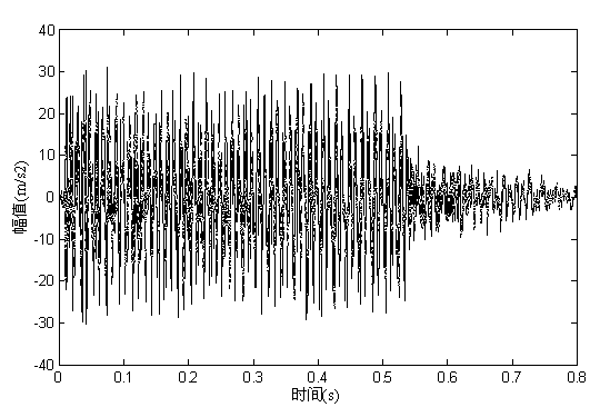
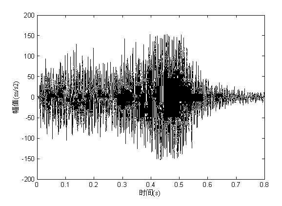
[0061] The short-circuit impact test was carried out with a 10kV distribution transformer of a power company as the test object. During the test, the low-voltage winding was short-circuited, the high-voltage B-phase winding was loaded with power, and 25 short-circuit impacts were performed. After each short-circuit test, the power was cut off to perform short-circuit impedance detection, and the vibration signal during each short-circuit impact state was recorded at the same time. figure 1 shows the vibration waveform when the transformer winding is in good condition, figure 2 It shows the vibration waveform when the working state of the transformer winding deteriorates. Follow the steps below to judge the working state of the winding when the transformer is short-circuited:

[0062] (1) Collect the vibration signal of the transformer box wall, and select the vibration signal within the time period of 0.8s;

[0063] (2) Extend the left endpoint of the above-mentioned vibrat...


PUM


Abstract

The invention discloses a transformer winding state diagnosis method. The transformer winding state diagnosis method comprises a first step of collecting vibration signals of a transformer box wall when a transformer is short-circuited; a second step of performing prolongation pretreatment on left end points and right end points of the vibration signals; a third step of decomposing the vibration signals undergone prolongation into a plurality of product function components; a fourth step of enabling all the product function components obtained by decomposition to undergo Hilbert transform, and obtaining a Hilbert spectrum of the vibration signals; a fifth step of obtaining a Hilbert marginal spectrum and Hilbert energy according to the Hilbert spectrum; and a sixth step of distinguishing a state of a transformer winding according to the Hilbert marginal spectrum and variations of the Hilbert energy.

Description

technical field [0001] The invention relates to a signal monitoring method, in particular to a diagnosis method for the winding state of a transformer. Background technique [0002] The transformer is one of the most important equipment in the power system, and its operation stability has a great influence on the safety of the power system. With the increasing capacity of my country's power grid, the short-circuit capacity is also increasing. The huge electromagnetic force generated by the surge current formed by the short-circuit of the transformer outlet poses a serious threat to the mechanical strength and dynamic stability of the transformer winding. At present, the operating environment of substation equipment and lines is not optimistic. The deformation of transformer winding caused by external short circuit is a relatively common fault in the process of transformer operation, which poses a great threat to the safe operation of the system. [0003] After the transform...

Claims


Application Information

Patent Timeline
IPC IPC(8): G01R31/06
Inventor 周求宽万军彪王丰华金之俭陆启宇
Owner ELECTRIC POWER RES INST STATE GRID JIANGXI ELECTRIC POWER CO
Learn More